Mounting a Compass (or GNSS/Compass)
Compass and GNSS/Compass modules should be mounted on the frame as far away from motor/ESC power lines and other sources of electromagnetic interference as possible, and oriented upright with the direction marker pointing towards the front of the vehicle. You should also configure PX4 to set the position of the receiver relative to the centre-of-gravity (CoG).
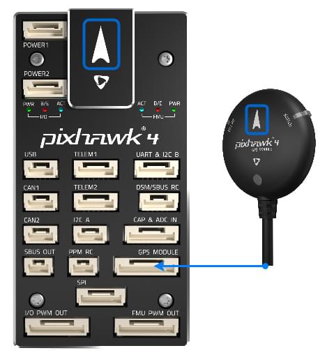
아래 다이어그램은 Pixhawk 4와 나침반의 전방 마커를 나타냅니다.
Compass Orientation
The compass should ideally be oriented so that it is upright and the direction marker is pointing towards the front of the vehicle (the default orientation), but if needed can be oriented at multiples of 45° from this attitude (in any axis) as defined in the standard MAVLink orientations (these follow the same frame convention as when orienting the flight controller).
The diagram below shows the heading marker on the Pixhawk 4 flight controller and compass.
PX4 will automatically detect the orientation for any of these standard orientations during compass calibration (by default).
The compass can also be mounted at any other "custom euler angles", but in this case you will need to manually configure the orientations. For more information see Setting the Compass Orientation in Flight Controller/Sensor Orientation.
Position
In order to compensate for the relative motion between the receiver and the CoG, you should configure the following parameters to set the offsets: SENS_GPS0_OFFX, SENS_GPS0_OFFY and SENS_GPS0_OFFZ.
This is important because the body frame estimated by the EKF will converge on the location of the GNSS module and assume it to be at the CoG. If the GNSS module is significantly offset from the CoG, then rotation around the COG will be interpreted as an altitude change, which in some flight modes (such as position mode) will result in unnecessary corrections.
It is particularly important if using RTK GNSS which has centimeter-level accuracy, because if the offsets are not set then GNSS measurements will often be rejected as inconsistent with the current EFK estimate.
Details
Explanation For example, if the GNSS module is 10cm above the CoG, and the IMU is located at the GoG, a pitch motion of 1 rad/s will create a GNSS velocity measurement of 10cm/s even though the CoG isn't moving. If the speed accuracy of the GNSS receiver is 1cm/s, the EKF might stop trusting the measurements because they appear inconsistent (wrong by 10x the accuracy). If the offsets are defined, the EKF will correct the measurements using the gyro data.