Holybro Kakute H7
PX4 v1.13WARNING
PX4 does not manufacture this (or any) autopilot. Contact the manufacturer for hardware support or compliance issues.
The Holybro Kakute H7 is full of features including dual plug-and-play 4in1 ESC ports, HD camera plug, barometer, OSD, 6x UARTs, full Blackbox MicroSD card slot, 5V and 9V BEC, easy soldering layout, and much more.
The Kakute H7 builds upon the best features of its predecessor, the Kakute F7, and further improves on hardware components and layout. Dual plug'n'play 4-in-1 ESC connectors simplify support for x8 and Octocopter configurations, keeping assembly simple and clean.
The board also has an on-board barometer, LED & buzzer pad, and I2C pad (SDA & SCL) for external GPS/Magnetometers.
INFO
This flight controller is manufacturer supported.
주요 특징
- MCU: STM32H743 32-bit processor running at 480 MHz
- IMU: MPU6000
- Barometer: BMP280
- OSD: AT7456E
- Onboard Bluetooth chip: Disabled with PX4
- 2x JST-SH1.0_8pin port (For Single or 4in1 ESCs, x8/Octocopter plug & play compatible)
- 1x JST-GH1.25_6pin port (For HD System like Caddx Vista & Air Unit)
- Battery input voltage: 2S - 8S
- BEC 5V 2A Cont.
- BEC 9V 1.5A Cont.
- Mounting: 30.5 x 30.5mm/Φ4mm hole with Φ3mm Grommets
- Dimensions: 35x35mm
- Weight: 8g
Where to Buy
The board can be bought from one of the following shops (for example):
TIP
The Kakute H7 is designed to work with the Tekko32 4-in-1 ESC and they can be bought in combination.
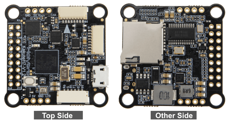
커넥터 및 핀
This is the silkscreen for the Kakute H7, showing the top of the board:

| 핀 | 기능 | 기본값 |
|---|---|---|
| B+ | Battery positive voltage (2S-8S) | |
| SDA, SCL | I2C 연결(주변장치용) | |
| 5V | 5V 출력 (최대 2A) | |
| 3V3 | 3.3V output (0.25A max) | |
| VI | FPV 카메라의 비디오 입력 | |
| VO | 비디오 송신기로 비디오 출력 | |
| CAM | To camera OSD control | |
| G 또는 GND | 접지 | |
| RSI | 수신기에서 아날로그 RSSI(0-3.3V) 입력 | |
| R1, T1 | UART1 RX 및 TX | TELEM1 |
| R3, T3 | UART3 RX 및 TX | NuttX 디버그 콘솔 |
| R4, T4 | UART4 RX 및 TX | GPS1 |
| R6, T6 | UART6 RX and TX (R6 also located in the GH plug) | RC 포트 |
| R7 | UART7 RX (RX is located in the plugs for use with 4-in-1 ESCs) | DShot 텔레메트리 |
| LED | WS2182 주소 지정이 가능한 LED 신호 와이어(테스트되지 않음) | |
| Z- | 피에조 부저 네거티브 레그(부저 포지티브 레그를 5V 패드에 연결) | |
| M1에서 M4 | 모터 신호 출력 (4-in-1 ESC에서 사용하기 위해 플러그에 위치) | |
| M5 to M8 | 모터 신호 출력 (4-in-1 ESC에서 사용하기 위해 플러그에 위치) | |
| Boot | 부트로더 버튼 |
PX4 Bootloader Update
The board comes pre-installed with Betaflight. Before PX4 firmware can be installed, the PX4 bootloader must be flashed. Download the kakuteh7_bl.hex bootloader binary and read this page for flashing instructions.
펌웨어 빌드
To build PX4 for this target:
sh
make holybro_kakuteh7_default펌웨어 설치
펌웨어는 일반적인 방법으로 설치할 수 있습니다.
소스 빌드 및 업로드
shmake holybro_kakuteh7_default uploadLoad the firmware using QGroundControl. 미리 빌드된 펌웨어나 사용자 지정 펌웨어를 사용할 수 있습니다.
INFO
If you are loading the pre-built firmware via QGroundControl, you must use QGC Daily or QGC version newer than 4.1.7.
PX4 설정
In addition to the basic configuration, the following parameters are important:
| 매개변수 | 설정 |
|---|---|
| SYS_HAS_MAG | 보드에 내부 자력계가 없기 때문에 비활성화하여야 합니다. 외부 자력계를 연결하여 활성화 할 수 있습니다. |
시리얼 포트 매핑
| UART | 장치 | 포트 |
|---|---|---|
| USART1 | /dev/ttyS0 | TELEM1 |
| USART2 | /dev/ttyS1 | TELEM2 |
| USART3 | /dev/ttyS2 | 디버그 콘솔 |
| UART4 | /dev/ttyS3 | GPS1 |
| USART6 | /dev/ttyS4 | RC SBUS |
| UART7 | /dev/ttyS5 | ESC 텔레메트리(DShot) |
Using TELEM2 (USART2)
The TELEM2 port (USART2) has no exposed solder pads as it is intended for use with Bluetooth telemetry (this does not work with PX4).
You can expose the solder pads and use the port by removing the two resistors marked with an X. No other configuration should be required.

디버그 포트
시스템 콘솔
UART3 RX and TX are configured for use as the System Console.
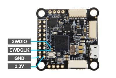
SWD
The SWD interface (JTAG) pins are:
SWCLK: Test Point 2 (Pin 72 on the CPU)SWDIO: Test Point 3 (Pin 76 on CPU)GND: As marked on boardVDD_3V3: As marked on board
These are shown below.