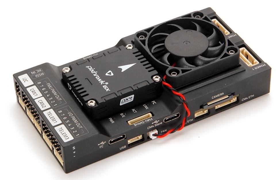
Holybro Pixhawk RPi CM4 Baseboard
The Holybro Pixhawk RPi CM4 Baseboard is a single-board solution that pre-integrates a (swappable) Pixhawk flight controller with the Raspberry Pi CM4 companion computer ("RPi"). The baseboard has a compact form factor with all the connections needed for development.
The flight controller module is internally connected to RPi CM4 through TELEM2, but may alternatively be connected using Ethernet with the provided external cable.
This baseboard is plug-in compatible with Holybro Pixhawk 5X, Holybro Pixhawk 6X, and any other Pixhawk controller that follows the Pixhawk Autopilot Bus Standard guidelines for mechanical compatibility across vendors.
INFO
The board follows the Pixhawk Connector Standard and Pixhawk Autopilot Bus Standard (including the guidelines for "mechanical compatibility across vendors").
Purchase
Holybro Pixhawk RPi CM4 Baseboard (www.holybro.com)
The baseboard can be purchased with or without an RPi CM4 and/or flight controller:
- The Raspberry Pi CM4 (CM4008032) supplied by Holybro has the following specification:
- RAM: 8GB
- eMMC: 32GB
- Wireless: No
- The recommended minimum specification for the RPi CM4 is:
- RAM: 4GB (or 8GB)
- eMMC: 16GB
- Wireless: Yes
- The Raspberry Pi CM4 (CM4008032) supplied by Holybro has the following specification:
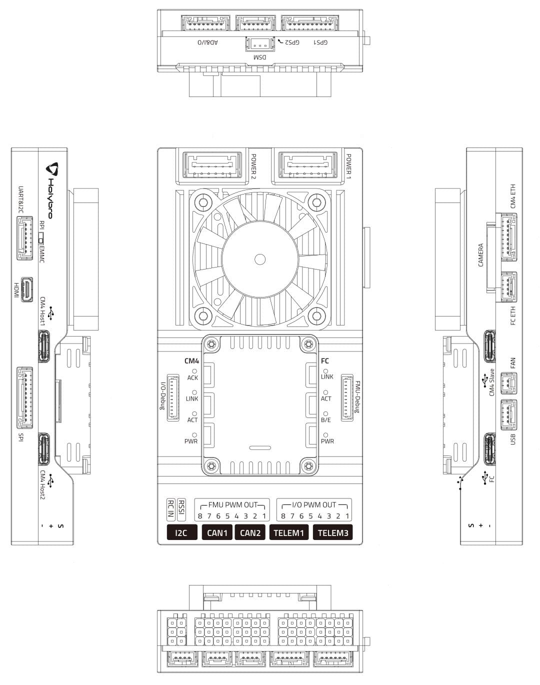
Connections & Ports
INFO
The Holybro Documentation has more detailed (and possibly more "up to date") port and connection information.
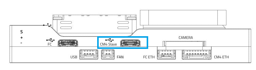
The diagram below shows all the connectors and ports on the baseboard.
RPi CM4 & FC Serial Connection
The flight controller TELEM2 port is internally connected to RPi CM4 as shown:
| RPi CM4 | FC TELEM2 (FMU) |
|---|---|
| GPIO14 | TXD |
| GPIO15 | RXD |
| GPIO16 | CTS |
| GPIO17 | RTS |
INFO
The connection must be also be configured in both RPi and PX4 (unless Ethernet is used instead).
Installing the Flight Controller
A plug-compatible flight controller such as Holybro Pixhawk 5X and Holybro Pixhawk 6X can simply be pushed into the module slot.
Flight controllers that have a different form factor will need additional wiring.
Installing the RPi CM4 Companion
This section shows how to install/attach an RPi CM4 to the baseboard.
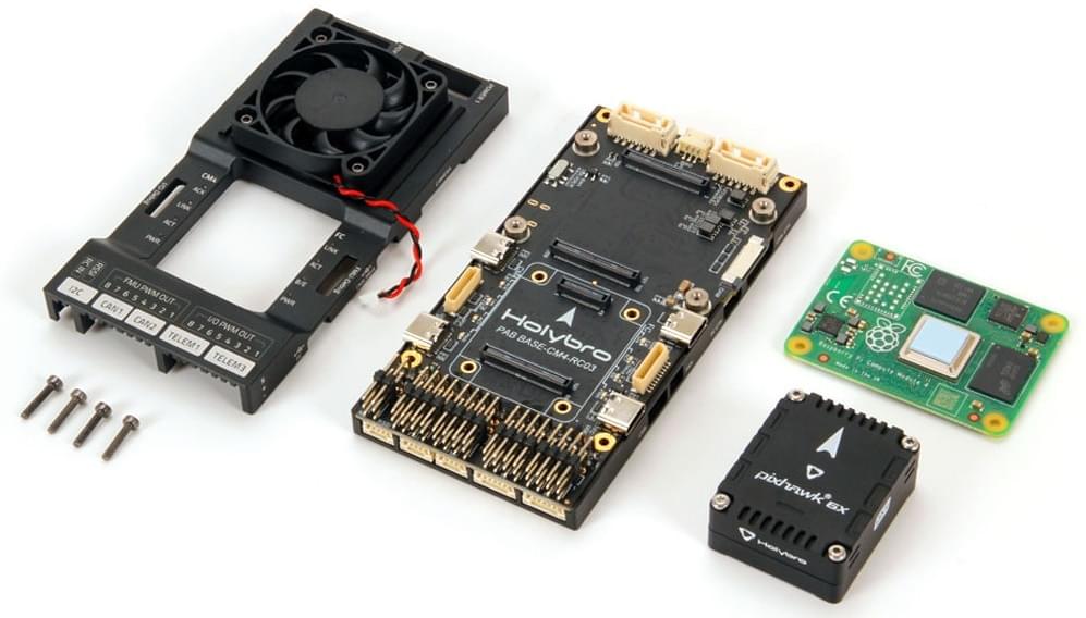
To install the RPi CM4 companion computer:
Disconnect the
FANwiring.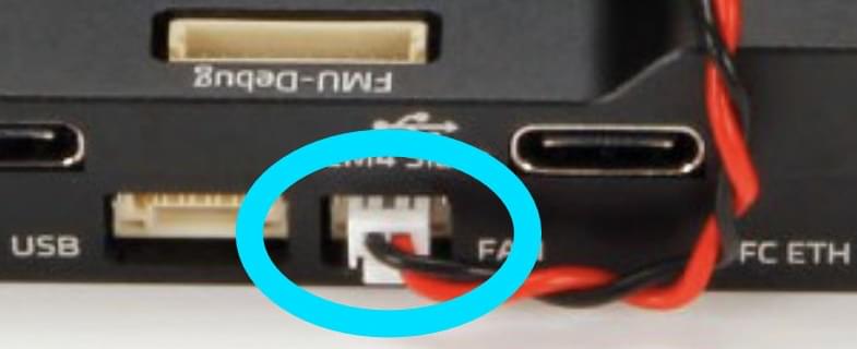
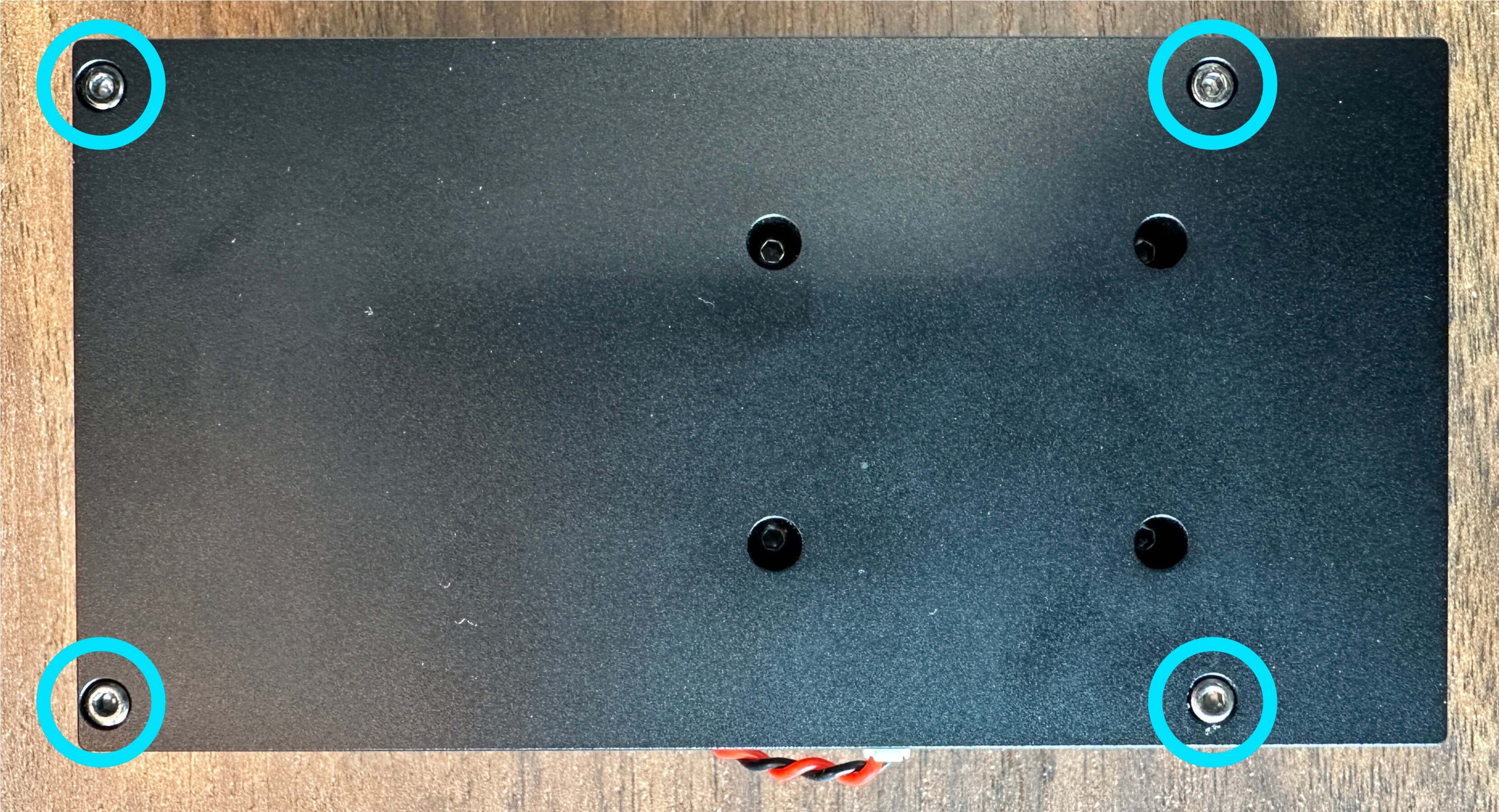
Remove these 4 screws on the back side of the baseboard.
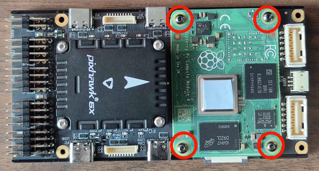
Remove the baseboard case, install the CM4, and use the 4 screws to attach it (as shown):
Reattach the cover.
Power Module Wiring
The PM03D power module is supplied with the board.
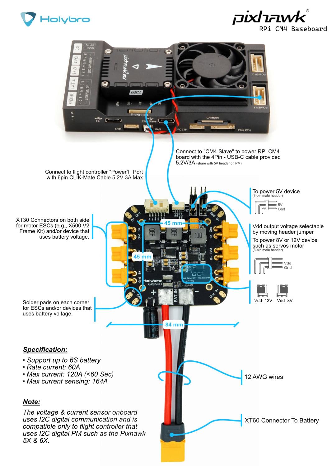
The RPi CM4 and flight controller must be powered separately:
- The flight controller is powered via the CLIK-Mate cable to
POWER1orPOWER2port - The RPi CM4 is powered by the
USB C(CM4 Slave) connection. You can also use your own power supply to power the RPi CM4 baseboard.
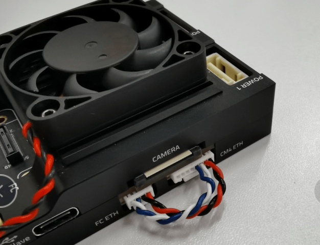
The image below shows the wiring in greater detail.
Flashing the RPi CM4
This section explains how you install your preferred Linux distro, such as "Raspberry Pi OS 64bit" onto the RPi EMCC.
Notes:
- If you are using PX4, you will need to use PX4 version 1.13.1 or newer for PX4 to recognize this baseboard.
- The fan does not indicate if the RPi CM4 is powered/running or not.
- The power module plugged into Power1/2 does not power the RPi part. You can use the additional USB-C Cable from the PM03D power module to the CM4 Slave USB-C port.
- The Micro-HDMI port is an output port.
- RPi CM4 boards that do not have WiFi device will not connect automatically. In this case you will need to plug it into a router or plug a compatible WiFi dongle into the CM4 Host ports.
Flash EMMC
To flash a RPi image onto EMMC.
Switch Dip-Switch to
RPI.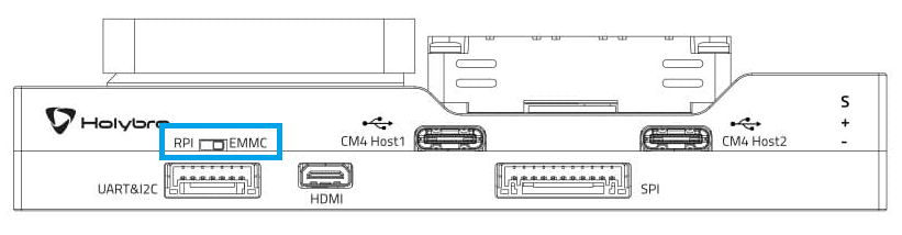
Connect computer to USB-C CM4 Slave port used to power & flash the RPi.
Get
usbboot, build it and run it.shsudo apt install libusb-1.0-0-dev git clone --depth=1 https://github.com/raspberrypi/usbboot cd usbboot make sudo ./rpibootYou can now install your preferred Linux distro using The
rpi-imager. Make sure you add WiFi and SSH settings (hidden behind the gear/advanced symbol).shsudo apt install rpi-imager rpi-imagerOnce done, unplugging USB-C CM4 Slave (this will unmount the volumes, and power off the CM4).
Switch Dip-Switch back to
EMMC.Power on CM4 by providing power to USB-C CM4 Slave port.
To check if it's booting/working you can either:
- Check there is HDMI output
- Connect via SSH (if set up in rpi-imager, and WiFi is available).
Configure PX4 to CM4 MAVLink Serial Connection
INFO
If you are using Ethernet to connect the FC and RPi, this setup is not needed.
The Pixhawk FC module is internally connected to the RPi CM4 using TELEM2 (/dev/ttyS4). The FC and RPi CM4 must both be configured to communicate over this port.
FC Serial Port Setup
The FC should be set up to connect to the TELEM2 port correctly by default. If not, you can configure the port using the parameters as shown.
To enable this MAVLink instance on the FC:
Connect a computer running QGroundControl via USB Type C port on the baseboard labeled
FC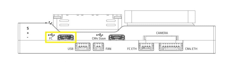
MAV_1_CONFIG=102MAV_1_MODE = 2SER_TEL2_BAUD=921600
Reboot the FC.
RPi Serial Port Setup
On the RPi side:
Connect to the RPi (using WiFi, a router, or a WiFi Dongle).
Enable the RPi serial port by running
RPi-config- Go to
3 Interface Options, thenI6 Serial Port. Then choose:login shell accessible over serial → Noserial port hardware enabled→Yes
- Go to
Finish, and reboot. This will add
enable_uart=1to/boot/config.txt, and removeconsole=serial0,115200from/boot/cmdline.txt.Now MAVLink traffic should be available on
/dev/serial0at a baudrate of 921600.
Try out MAVSDK-Python
Make sure the CM4 is connected to the internet, e.g. using a WiFi, or Ethernet.
Install MAVSDK Python:
shpython3 -m pip install mavsdkCopy an example from the MAVSDK-Python examples.
Change the
system_address="udp://:14540"tosystem_address="serial:///dev/serial0:921600"Try out the example. Permission for the serial port should already be available through the
dialoutgroup.
Ethernet Connection (Optional)
The flight controller module is internally connected to RPi CM4 from TELEM2 (serial).
You can also set up a local Ethernet connection between them using the supplied cable. Ethernet connectivity provides a fast, reliable, and flexible communication alternative to using USB or other serial connections.
INFO
For general Ethernet setup information see: PX4 Ethernet Setup.
The setup here is much the same, except that we have used the following netplan config on PX4:
network:
  version: 2
  renderer: NetworkManager
  ethernets:
    eth0:
      addresses:
        - 10.41.10.1/24
      nameservers:
        addresses: [10.41.10.1]
      routes:
        - to: 10.41.10.0/24  # Local route to access devices on this subnet
          scope: link        # Scope link to restrict it to local subnet
This sets eth0 as our channel for the local Ethernet link from the RPi (instead of enp2s0, which is assumed in Ethernet Setup).
Note that we could have used WiFi for the link, but by setting up a dedicated route we leave our WiFi free for Internet comms.
Connect the Cable
To set up a local ethernet connection between CM4 and the flight computer, the two Ethernet ports need to be connected using the provided 8 pin to 4 pin connector.
The pinout of the cable is:
| CM4 Eth 8 Pin | FC ETH 4 Pin |
|---|---|
| A | B |
| B | A |
| C | D |
| D | C |
| - | 해당없음 |
| - | 해당없음 |
| - | 해당없음 |
| - | 해당없음 |
IP Setup on CM4
Since there is no DHCP server active in this configuration, the IP addresses have to be set manually:
First, connect to the CM4 via SSH by connecting to the CM4's WiFi (or use a WiFi dongle). Once the Ethernet cables are plugged in, the eth0 network interface seems to switch from DOWN to UP.
You can check the status using:
ip address show eth0You can also try to enable it manually:
sudo ip link set dev eth0 upThis sets a link-local address. For this example it looks like this:
$: ip address show eth0
2: eth0: <BROADCAST,MULTICAST,UP,LOWER_UP> mtu 1500 qdisc mq state UP group default qlen 1000
    link/ether e4:5f:01:bf:e0:17 brd ff:ff:ff:ff:ff:ff
    inet 10.41.10.1/24 brd 10.41.10.255 scope global noprefixroute eth0
       valid_lft forever preferred_lft forever
    inet6 fe80::e65f:1ff:febf:e017/64 scope link
       valid_lft forever preferred_lft forever
This means the CM4's Ethernet IP is 10.41.10.1 .
Ping Test
First ping PX4 from the CM4 (using the PX4's default address):
$ ping 10.41.10.2Should give something like:
PING 10.41.10.2 (10.41.10.2) 56(84) bytes of data.
64 bytes from 10.41.10.2: icmp_seq=1 ttl=64 time=0.187 ms
64 bytes from 10.41.10.2: icmp_seq=2 ttl=64 time=0.109 ms
64 bytes from 10.41.10.2: icmp_seq=3 ttl=64 time=0.091 ms
^C
--- 10.41.10.2 ping statistics ---
3 packets transmitted, 3 received, 0% packet loss, time 2049ms
rtt min/avg/max/mdev = 0.091/0.129/0.187/0.041 ms
INFO
If this step fails, check if a firewall is active.
Then ping the CM4 from the flight controlle. Enter the following command in the Nuttx Shell:
nsh> ping 10.41.10.1This should result in output like:
PING 10.41.10.1 56 bytes of data
56 bytes from 10.41.10.1: icmp_seq=0 time=0.0 ms
56 bytes from 10.41.10.1: icmp_seq=1 time=0.0 ms
56 bytes from 10.41.10.1: icmp_seq=2 time=0.0 ms
56 bytes from 10.41.10.1: icmp_seq=3 time=0.0 ms
56 bytes from 10.41.10.1: icmp_seq=4 time=0.0 ms
56 bytes from 10.41.10.1: icmp_seq=5 time=0.0 ms
56 bytes from 10.41.10.1: icmp_seq=6 time=0.0 ms
56 bytes from 10.41.10.1: icmp_seq=7 time=0.0 ms
56 bytes from 10.41.10.1: icmp_seq=8 time=0.0 ms
56 bytes from 10.41.10.1: icmp_seq=9 time=0.0 ms
10 packets transmitted, 10 received, 0% packet loss, time 10010 ms
rtt min/avg/max/mdev = 0.000/0.000/0.000/0.000 ms
MAVLink/MAVSDK Test
For this, we need to set the MAVLink instance to send traffic to the CM4's IP address:
For an initial test we can do:
mavlink start -o 14540 -t 10.41.10.1This will send MAVLink traffic on UDP to port 14540 (the MAVSDK/MAVROS port) to that IP which means MAVSDK can just listen to any UDP arriving at that default port.
To run a MAVSDK example, install mavsdk via pip, and try out an example from MAVSDK-Python/examples.
XRCE-Client Ethernet Setup
Next we enable XRCE-DDS on the new Ethernet Link.
You can modify the required parameters in QGroundControl parameter editor, or using param set in the MAVLINK shell. Below we show the settings assuming you're setting the parameters using the shell.
First ensure MAV_2_CONFIG is not set to use the Ethernet port (1000) as this would clash with XRCE-DDS (see enable MAVLINK on Ethernet):
nsh>
param set MAV_2_CONFIG     0           # Change to 0 IFF value is 1000
Then enable uXRCE-DDS on the Ethernet port (see starting uXRCE-DDS client):
param set UXRCE_DDS_AG_IP  170461697   # The int32 version of 10.41.10.1
param set UXRCE_DDS_CFG    1000        # Set Serial Configuration for uXRCE-DDS Client to Ethernet
param set UXRCE_DDS_DOM_ID 0           # Set uXRCE-DDS domain ID
param set UXRCE_DDS_KEY    1           # Set uXRCE-DDS session key
param set UXRCE_DDS_PRT    8888        # Set uXRCE-DDS UDP port
param set UXRCE_DDS_PTCFG  0           # Set uXRCE-DDS participant configuration
param set UXRCE_DDS_SYNCC  0           # Disable uXRCE-DDS system clock synchronization
param set UXRCE_DDS_SYNCT  1           # Enable uXRCE-DDS timestamp synchronization
Then run the Agent:
MicroXRCEAgent udp4 -p 8888And such output is expected if everything is set up correctly:
[1731210063.537033] info     | UDPv4AgentLinux.cpp | init                     | running...             | port: 8888
[1731210063.538279] info     | Root.cpp           | set_verbose_level        | logger setup           | verbose_level: 4
[1731210066.577413] info     | Root.cpp           | create_client            | create                 | client_key: 0x00000001, session_id: 0x81
[1731210066.577515] info     | SessionManager.hpp | establish_session        | session established    | client_key: 0x00000001, address: 10.41.10.2:58900
[1731210066.583965] info     | ProxyClient.cpp    | create_participant       | participant created    | client_key: 0x00000001, participant_id: 0x001(1)
[1731210066.584754] info     | ProxyClient.cpp    | create_topic             | topic created          | client_key: 0x00000001, topic_id: 0x800(2), participant_id: 0x001(1)
[1731210066.584988] info     | ProxyClient.cpp    | create_subscriber        | subscriber created     | client_key: 0x00000001, subscriber_id: 0x800(4), participant_id: 0x001(1)
[1731210066.589864] info     | ProxyClient.cpp    | create_datareader        | datareader created     | client_key: 0x00000001, datareader_id: 0x800(6), subscriber_id: 0x800(4)
[1731210066.591007] info     | ProxyClient.cpp    | create_topic             | topic created          | client_key: 0x00000001, topic_id: 0x801(2), participant_id: 0x001(1)
[1731210066.591164] info     | ProxyClient.cpp    | create_subscriber        | subscriber created     | client_key: 0x00000001, subscriber_id: 0x801(4), participant_id: 0x001(1)
[1731210066.591912] info     | ProxyClient.cpp    | create_datareader        | datareader created     | client_key: 0x00000001, datareader_id: 0x801(6), subscriber_id: 0x801(4)
[1731210066.592701] info     | ProxyClient.cpp    | create_topic             | topic created          | client_key: 0x00000001, topic_id: 0x802(2), participant_id: 0x001(1)
[1731210066.592846] info     | ProxyClient.cpp    | create_subscriber        | subscriber created     | client_key: 0x00000001, subscriber_id: 0x802(4), participant_id: 0x001(1)
[1731210066.593640] info     | ProxyClient.cpp    | create_datareader        | datareader created     | client_key: 0x00000001, datareader_id: 0x802(6), subscriber_id: 0x802(4)
[1731210066.594749] info     | ProxyClient.cpp    | create_topic             | topic created          | client_key: 0x00000001, topic_id: 0x803(2), participant_id: 0x001(1)
[1731210066.594883] info     | ProxyClient.cpp    | create_subscriber        | subscriber created     | client_key: 0x00000001, subscriber_id: 0x803(4), participant_id: 0x001(1)
[1731210066.595592] info     | ProxyClient.cpp    | create_datareader        | datareader created     | client_key: 0x00000001, datareader_id: 0x803(6), subscriber_id: 0x803(4)
[1731210066.596188] info     | ProxyClient.cpp    | create_topic             | topic created          | client_key: 0x00000001, topic_id: 0x804(2), participant_id: 0x001(1)
[1731210066.596334] info     | ProxyClient.cpp    | create_subscriber        | subscriber created     | client_key: 0x00000001, subscriber_id: 0x804(4), participant_id: 0x001(1)
[1731210066.597046] info     | ProxyClient.cpp    | create_datareader        | datareader created     | client_key: 0x00000001, datareader_id: 0x804(6), subscriber_id: 0x804(4)
See Also
- Get The Pixhawk Raspberry Pi CM4 Baseboard By Holybro Talking With PX4 (px4.io blog):
- Tutorial showing how to connect Pixhawk 6X + Raspberry Pi on CM4 baseboard via wired Ethernet.