SWD Debug Port
PX4 runs on ARM Cortex-M microcontrollers, which contain dedicated hardware for interactive debugging via the Serial Wire Debug (SWD) interface and non-invasive profiling and high-bandwidth tracing via the Serial Wire Output (SWO) and TRACE pins.
The SWD debug interface allows direct, low-level, hardware access to the microcontroller's processor and peripherals, so it does not depend on any software on the device. Therefore it can be used to debug bootloaders and operating systems such as NuttX.
Debug Signals
Four signals are required for debugging (in bold) while the rest is recommended.
| 명칭 | 형식 | 설명 |
|---|---|---|
| GND | 전원 | Shared potential, common ground. |
| VREF | 전원 | The target reference voltage allows the debug probe to use level shifters on the signals. |
| SWDIO | I/O | Serial Wire Debug data pin. |
| SWCLK | Input | Serial Wire Debug clock pin. |
| nRST | Input | The reset pin is optional (n = active low). |
| SWO | 출력 | Single wire trace asynchronous data out can output ITM and DWT data. |
| TRACECK | 출력 | Trace clock for parallel bus. |
| TRACED[0-3] | 출력 | Trace synchronous data bus with 1, 2, or 4 bits. |
The hardware reset pin is optional, as most devices can also be reset via the SWD lines. However, quickly resetting the device via a button can be great for development.
The SWO pin can emit low-overhead, real-time profiling data with nanosecond timestamping and is therefore strongly recommended to have accessible for debugging.
The TRACE pins require specialized debug probes to deal with the high bandwidth and subsequent datastream decoding. They are usually not accessible and are typically only used to debug very specific timing issues.
Autopilot Debug Ports
Flight controllers commonly provide a single debug port that exposes both the SWD Interface and System Console.
The Pixhawk Connector Standards formalize the port that must be used in each FMU version. However there are still many boards that use different pinouts or connectors, so we recommend you check the documentation for your autopilot to confirm port location and pinout.
The debug port location and pinouts for a subset of autopilots are linked below:
Pixhawk Connector Standard Debug Ports
The Pixhawk project has defines a standard pinout and connector type for different Pixhawk FMU releases:
TIP
Check your specific board to confirm the port used.
| FMU 버전 | Pixhawk Version | 디버그 포트 |
|---|---|---|
| FMUv2 | Pixhawk / Pixhawk 1 | 10핀 ARM 디버그 |
| FMUv3 | Pixhawk 2 | 6핀 SUR 디버그 |
| FMUv4 | Pixhawk 3 | Pixhawk Debug Mini |
| FMUv5 | Pixhawk 4 FMUv5 | Pixhawk Debug Mini |
| FMUv5X | Pixhawk 5X | Pixhawk Debug Full |
| FMUv6 | Pixhawk 6 | Pixhawk Debug Full |
| FMUv6X | Pixhawk 6X | Pixhawk Debug Full |
| FMUv6X-RT | Pixhawk 6X-RT | Pixhawk Debug Full |
INFO
There FMU and Pixhawk versions are (only) consistent after FMUv5X.
Pixhawk Debug Mini
The Pixhawk Connector Standard defines the Pixhawk Debug Mini, a 6-Pin SH Debug Port that provides access to both SWD pins and the System Console.
This is used in FMUv4 and FMUv5.
The pinout is as shown below (pins required for debugging are bold):
| 핀 | 신호 |
|---|---|
| 1 | VREF |
| 2 | 콘솔 TX |
| 3 | 콘솔 RX |
| 4 | SWDIO |
| 5 | SWDCLK |
| 6 | GND |
The debug port definition includes the following solder pads (on board next to connector):
| 패드 | 신호 | 전압 |
|---|---|---|
| 1 | nRST | +3.3V |
| 2 | GPIO1 | +3.3V |
| 3 | GPIO2 | +3.3V |
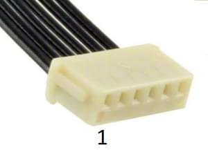
The socket is a 6-pin JST SH - Digikey number: BM06B-SRSS-TBT(LF)(SN) (vertical mount), SM06B-SRSS-TBT(LF)(SN) (side mount).
You can connect to the debug port using a cable like this one.
Pixhawk Debug Full
The Pixhawk Connector Standard defines Pixhawk Debug Full, a 10-Pin SH Debug Port that provides access to both SWD pins and the System Console. This essentially moves the solder pads from beside the Pixhawk Debug Mini into the connector, and also adds an SWO pin.
This port is specified for use in FMUv5x, FMUv6, FMUv6x.
The pinout is as shown below (pins required for debugging are bold):
| 핀 | 신호 |
|---|---|
| 1 | VREF |
| 2 | 콘솔 TX |
| 3 | 콘솔 RX |
| 4 | SWDIO |
| 5 | SWDCLK |
| 6 | SWO |
| 7 | GPIO1 |
| 8 | GPIO2 |
| 9 | nRST |
| 10 | GND |
The GPIO1/2 pins are free pins that can be used to generate signals in software for timing analysis with a logic analyzer.
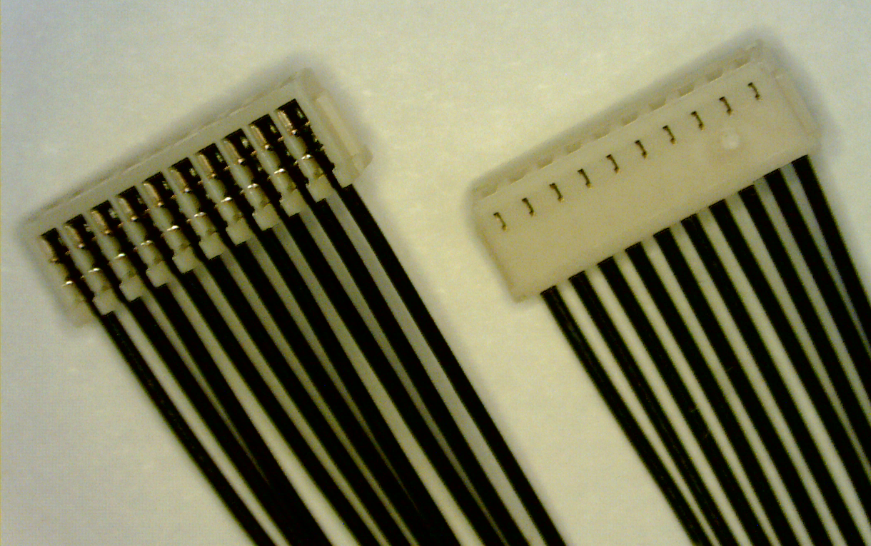
The socket is a 10-pin JST SH - Digikey number: BM10B-SRSS-TB(LF)(SN) (vertical mount) or SM10B-SRSS-TB(LF)(SN) (side mount).
You can connect to the debug port using a cable like this one.
Debug Probes for PX4 Hardware
Flight controllers commonly provide a single debug port that exposes both the SWD Interface and System Console.
There are several debug probes that are tested and supported for connecting to one or both of these interfaces:
- SEGGER J-Link: commercial probe, no built-in serial console, requires adapter.
- Black Magic Probe: integrated GDB server and serial console, requires adapter.
- STLink: best value, integrated serial console, adapter must be soldered.
- MCU-Link: best value, integrated serial console, requires adapter.
An adapter to connect to the debug port may come with your flight controller or debug probe. Other options are given below.
Debug Adapters
Holybro Pixhawk Debug Adapter
The Holybro Pixhawk Debug Adapter is highly recommended when debugging controllers that use one of the Pixhawk-standard debug connectors.
It is the easiest way to connect:
- Flight controllers that use either the Pixhawk Debug Full (10-pin SH) or Pixhawk Debug Mini (6-pin SH) debug port.
- SWD debug probes that support the 10-pin ARM compatible interface standard used by the Segger JLink EDU mini or 20-pin compatible with the Segger JLink or STLink.
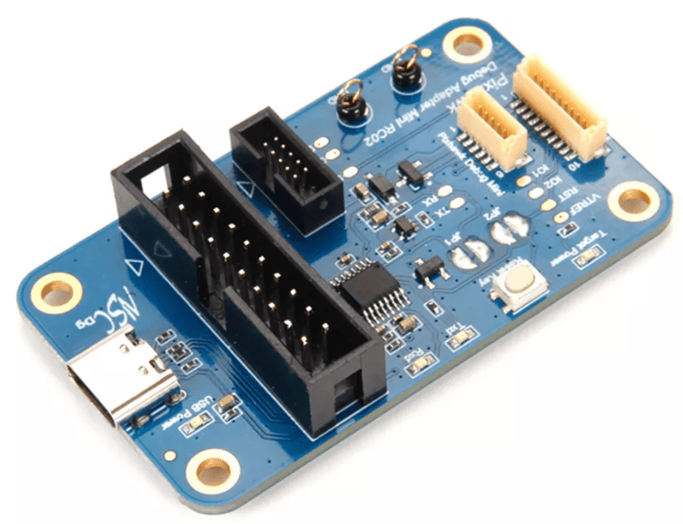
CUAV C-ADB Pixhawk Debug Adapter
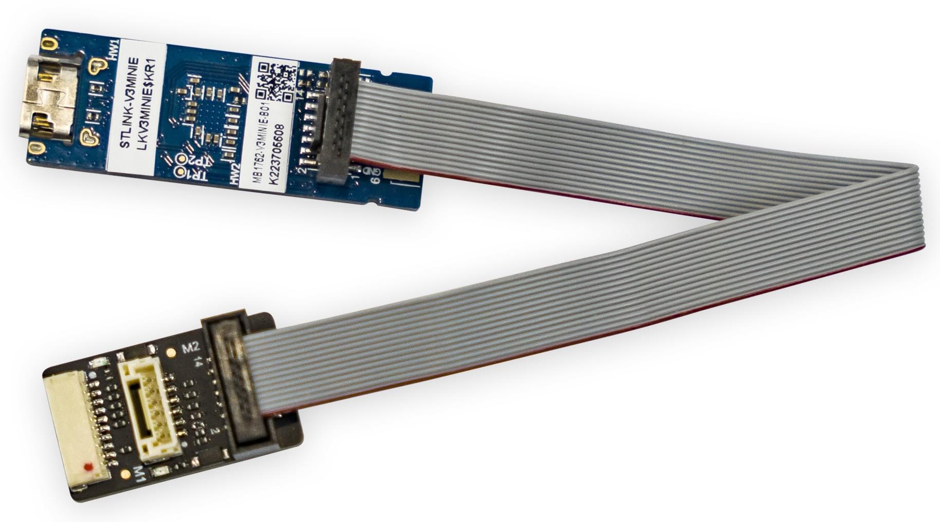
The CUAV C-ADB Secondary Development Pixhawk Flight Controller Debug Adapter comes with an STLinkv3-MINIE Debug Probe.
This has a ports for connecting to the Pixhawk Debug Full (10-pin SH) and CUAV-standard DSU interface (but not the Pixhawk Debug Mini (6-pin SH)).
The M2 connector on the adaptor is 14-pin CN4 STDC14 (see the STLinkv3-MINIE User Manual for more information). The cable used to connect the M2 and the STLinkv3-MINIE comes with the adaptor.
Debug Probe Adapters
Some SWD debug probes come with adapters/cables for connecting to common Pixhawk debug ports. Probes that are known to come with connectors are listed below:
- Zubax BugFace BF1: comes with a connector for attaching to the Pixhawk Debug Mini
Board-specific Adapters
Some manufacturers provide cables to make it easy to connect the SWD interface and System Console.
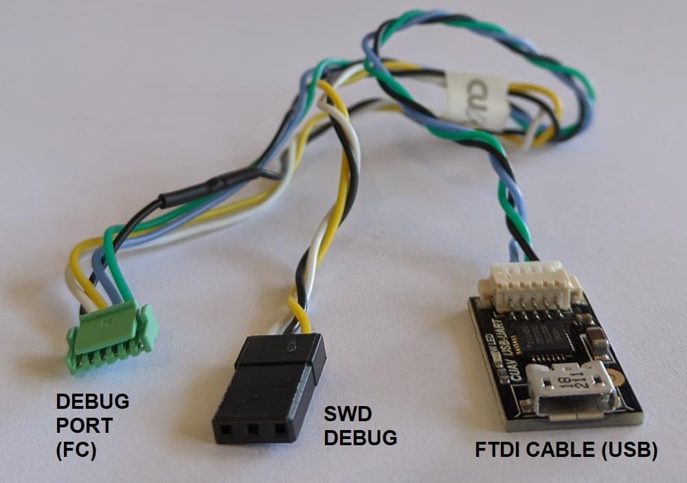
- CUAV V5nano and CUAV V5+ include this debug cable:
Custom Cables
You can also create custom cables for connecting to different boards or probes:
- Connect
SWDIO,SWCLKandGNDpins on the debug probe to the corresponding pins on the debug port. - Connect the VREF pin, if supported by the debug probe.
- Connect the remaining pins, if present.
See the STLinkv3-MINIE for a guide on how to solder a custom cable.
TIP
Where possible, we highly recommend that you create or obtain an adapter board rather than custom cables for connecting to SWD/JTAG debuggers and computers. This reduces the risk or poor wiring contributing to debugging problems, and has the benefit that adapters usually provide a common interface for connecting to multiple popular flight controller boards.