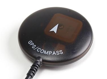
GPS와 나침반
A GNSS system is needed for missions, and some other automatic and manual/assisted modes. PX4는 u-blox, MTK Ashtech 또는 Emlid 프로토콜이나 UAVCAN 통신 수신기를 사용하여 글로벌 내비게이션 위성시스템(GNSS)(GPS, GLONASS, Galileo, BeiDou, QZSS 및 SBAS 포함)을 지원합니다.
Up to two GPS modules can be connected using either a UART or the CAN bus:
- A primary GNSS module that usually also includes a compass/magnetometer, buzzer, safety switch, and UI LED.
- An optional secondary GNSS/compass module that is used as a fallback. This may include a buzzer, safety switch, LEDs, but these are not used by PX4.
INFO
PX4 also supports Real Time Kinematic (RTK) and Post-Processing Kinematic (PPK) GNSS Receivers, which extend GNSS systems to centimetre-level precision.
지원되는 GNSS와 나침반
PX4는 u-blox, MTK Ashtech 또는 Emlid 프로토콜 또는 UAVCAN 통신 장치에서 작동합니다.
This table contains non-RTK GNSS units (most of which also have a compass). These have been tested by the PX4 dev team, or which are popular within the PX4 community.
Notes:
- ✓ or a specific part number indicate that a features is supported, while ✘ or empty show that the feature is not supported. "?"는 "알 수 없음"을 나타냅니다.
- Where possible and relevant the part name is used (i.e. ✓ in the GPS column indicates that a GPS module is present but the part is not known).
- The list may omit some discontinued hardware that is still supported (check earlier versions for info about discontinued modules). Removed items include:
- Here GPS
- Drotek DP0804
Mounting the GNSS/Compass
Most GNSS modules also contain a compass/magnetometer part (see link for calibration/setup information). 최대 4 개의 내외부 자력계를 연결할 수 있지만, 실제로는 하나만 헤딩 소스로 사용됩니다.
Mounting the Compass explains how to mount a GNSS module that has a compass.
하드웨어 설정
The hardware setup depends on the flight controller, the GNSS module, and the connection bus it supports - UART/I2C or CAN.
Pixhawk Standard Connectors
Connecting GNSS/Compass modules is easiest when using a flight controller that supports the Pixhawk connector standard. All flight controllers that follow this standard, including most Pixhawk Standard controllers (and many others) use the same port connectors and wiring for connecting GNSS modules. Because of this standardization, many popular GNSS/Compass modules plug directly into the flight controller "out of the box".
If you're using GNSS/Compass modules that connect via generic UARTs and serial protocols like I2C:
- The primary GNSS/Compass module should be connected to the 10-pin port labelled
GPS1,GPS&SAFETY, orGPS(this is port described as "Full GPS + Safety Switch Port" in the connector standard). The GPS should incorporate a buzzer, safety switch, and UI LED. - An (optional) secondary module can be connected to the 6-pin
GPS2port, if present (this is "Basic GPS Port" in the standard). - The ports are generally plug-n-play for u-blox modules (only).
INFO
The ports include a UART for the GNSS and an I2C port for connecting the Compass. The "Full GPS + Safety Switch Port" includes additional I2C connectors for LEDs, buzzer and safety switch. There is nothing to stop you from connecting the GPS pins to any other free UART as a GNSS port, and the compass or buzzer to an I2C port. However if you do this then you will need to configure the ports.
For DroneCAN GNSS/compass modules:
- DroneCan GPS modules are connected to CAN-bus ports, which are 4-pin ports labeled
CAN1orCAN2.
Other Flight Controllers/GNSS Modules
If you're working with a flight controller and GNSS module combination that does not comply with the Pixhawk connector standard then you will need to pay particular attention to the connector pinouts on the flight controller and the module. You may need to rewire/solder the connectors.
WARNING
Some flight controllers use ports that are software-compatible but not connector compatible (even if they use the same connector!) because they use different pin orderings.
The pinouts for the connector standard are documented in the standard. Pinouts for other controllers and the GNSS modules should be included in their manufacturer documentation.
GNSS 설정
The default configuration for GPS module connected via the GPS serial port is provided below. Additional device-specific configuration may be provided in PX4 or manufacturer device documentation (e.g. Trimble MB-Two > Configuration).
Primary GPS Configuration (UART)
Primary GPS configuration on Pixhawk is handled transparently for U-Blox GPS modules — simply connect the GPS module to the port labeled GPS1, GPS&SAFETY, or GPS (if there is only one GPS port), and everything should work.
The default Serial Port Configuration configures GPS1 as a GPS port using GPS_1_CONFIG, sets the protocol to u-blox with GPS_1_PROTOCOL, and a baud rate of 0: Auto with SER_GPS1_BAUD.
For GPS types like Trimble, Emlid, MTK, you will need to change the GPS_1_PROTOCOL appropriately. For Trimble MB-Two you will also need to modify SER_GPS1_BAUD to set the rate to 115200 baud.
Secondary GPS Configuration (UART)
To use a secondary GPS, you will generally attach it to the port named GPS2, if present, and otherwise attach it to any free UART port. The port may be pre-configured, but unlike the primary port, this is not guaranteed.
To ensure the port is set up correctly perform a Serial Port Configuration to assign GPS_2_CONFIG to the selected port.
The following steps show how to configure a secondary GPS on the GPS 2 port in QGroundControl:
Find and set the parameter GPS_2_CONFIG to GPS 2.
Open QGroundControl and navigate to the Vehicle Setup > Parameters section.
Select the GPS tab, then open the GPS_2_CONFIG parameter and select
GPS 2from the dropdown list.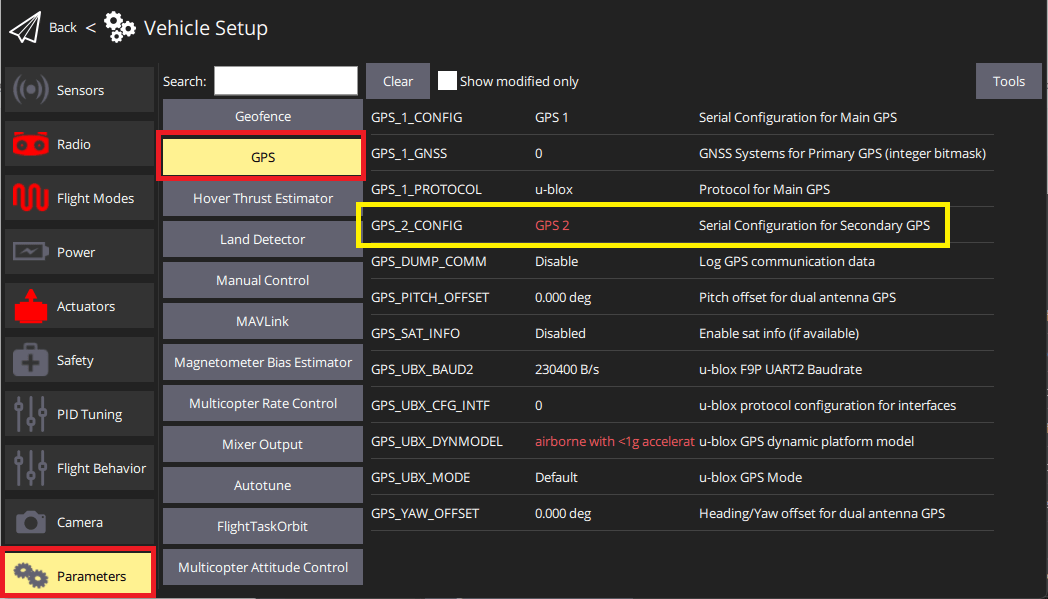
다른 매개변수를 표시하려면 기체를 재부팅하십시오.
Select the Serial tab, and open the SER_GPS2_BAUD parameter (
GPS 2port baud rate): set it to Auto (or 115200 for the Trimble).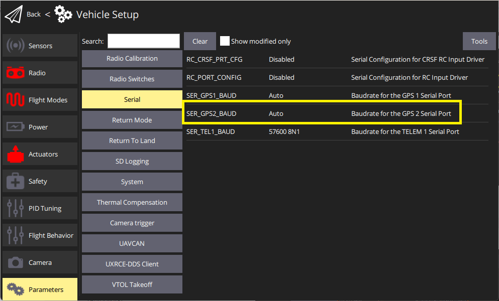
보조 GPS 포트를 설정 후 :
- 두 GPS 시스템의 데이터를 혼합하도록 ECL/EKF2 추정기를 설정합니다. For detailed instructions see: Using the ECL EKF > Dual Receivers.
DroneCAN GNSS Configuration
DroneCAN GNSS configuration is covered in the linked document (and in the documentation for specific modules).
GPS를 Yaw/Heading 소스로 설정
GPS can be used as a source for yaw fusion when using modules where yaw output is supported by the device. This is documented in RTK GPS > Configuring GPS as Yaw/Heading Source.
나침반 설정
Compass calibration for an included compass part is covered in: Compass Configuration.
GNSS Data Overview
PX4 uses the subset of information that can be provided by most GNSS modules. This is written to the SensorGps uORB message and used by the estimator as an input to global position estimation. It is also streamed via MAVLink using messages such as GPS_RAW_INT and GPS2_RAW.
Some of GNSS terms that are useful for interpreting the data include:
DOP: Dilution of position (dimensionless). This is a measure of the geometric quality of satellite positions and their effect on the precision of the GPS receiver's calculations.EPH: Standard deviation of horizontal position error (metres). This represents the uncertainty in the GPS fix latitude and longitude.EPV: Standard deviation of vertical position error (metres). This represents the uncertainty in the GPS fix altitude.
DOP vs EPH/EPV
DOP is a measure of the potential for high accuracy based on satellite positions. EPH/EPV are more comprehensive: they are direct estimates of the GPS position error and consider both satellite geometry and other error sources like signal noise and atmospheric effects. It is possible to have low DOP (good satellite geometry) but still have high EPH/EPV if there is significant signal noise or atmospheric interference.
EPH/EPV values therefore provide a more immediate and practical estimate of the actual GPS accuracy you can expect under current conditions.
GNSS Position Fusion
GNSS position fusion will not begin until yaw alignment is established. If a magnetometer is available, the EKF aligns yaw using the magnetic heading, allowing GPS position fusion to start soon after boot. If no magnetometer is present, the system must rely on GPS yaw (from a dual-antenna setup) or movement-based yaw estimation. Until one of these provides a valid heading, the EKF will not start GPS position fusion, and the vehicle will remain in a “no position” state even though attitude data is valid. This behavior prevents large position errors that could occur when the yaw reference is uncertain.
개발자 정보
- GPS/RTK-GPS
- 나침반
- Driver source code (Compasses)