Helicopter Configuration
This section contains topics related to helicopter configuration and tuning.
Supported Configurations
Supported helicopter configurations:
- Single main rotor with swash-plate controlled by up to 4 swash-plate servos and a mechanically uncoupled tail rotor driven by an ESC.
- Single main rotor with swash-plate controlled by up to 4 swash-plate servos and a mechanically coupled tail controlled by a servo.
Supported flight operations/features:
- Same as a multicopter.
- At the time of writing no autonomous/guided 3D flying with negative thrust is possible.
Setup
To setup and configure a helicopter:
Select a helicopter Airframe in QGroundControl. At time of writing there is only Generic Helicopter (Tail ESC) in the Helicopter group. This will configure the helicopter frame with a mechanically uncoupled tail (CA_AIRFRAME:
10: Helicopter (tail ESC)).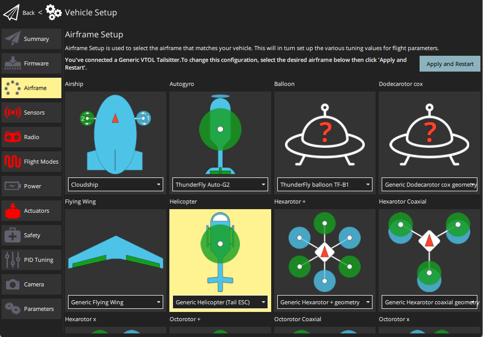
INFO
There is no separate airframe for the helicopter with tail servo. To select this configuration, set the parameter CA_AIRFRAME to Helicopter (tail Servo). The actuator configuration screen will then change to support this frame type.
Configure helicopter actuator geometry in Vehicle Setup > Actuators.
INFO
Actuator setup and testing is covered for most frames in Actuators. While that is referenced below, this is the main topic for helicopter setup information.
The geometry for a Generic Helicopter - with Tail ESC is shown below.
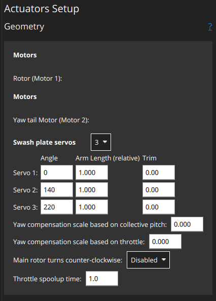
The motors have no configurable geometry:
Rotor (Motor 1): The main rotorYaw tail motor (Motor 2): The tail rotor
Swash plate servos:
3|4For each servo set:
Angle: Clockwise angle in degree on the swash plate circle at which the servo arm is attached starting from0pointing forwards. Example for a typical setup where three servos are controlling the swash plate equally distributed over the circle (360° / 3 =) 120° apart each which results in the angles:# Angle Servo 1 60° Servo 2 180° Servo 3 300° 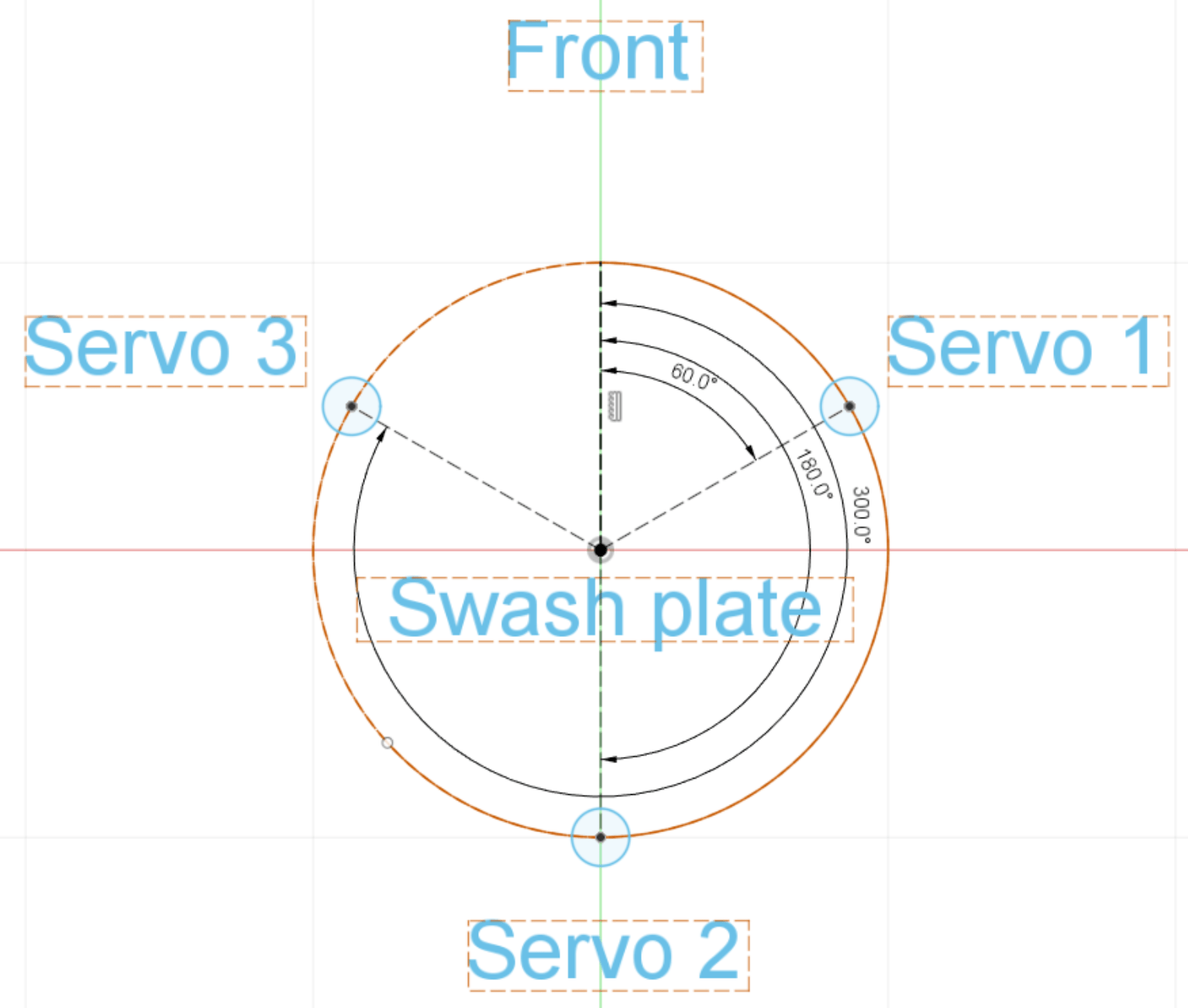
Arm Length (relative to each other): Radius from the swash plate center (top view). A shorter arm means the same servo motion moves the plate more. This allows the autopilot to compensate.Trim: Offset individual servo positions. This is only needed in rare case when the swash plate is not level even though all servos are centered.
Additional settings:
Yaw compensation scale based on collective pitch: How much yaw is feed forward compensated based on the current collective pitch.Main rotor turns counter-clockwise:Disabled(clockwise rotation) |EnabledThrottle spoolup time: Set value (in seconds) greater than the achievable minimum motor spool up time. A larger value may improve user experience.
Remove the rotor blades and propellers
Assign motors and servos to outputs and test (also in Actuator configuration):
- Assign the motors and servos to the outputs.
- Power the vehicle with a battery and use the actuator testing sliders to validate correct servo and motor assignment and direction.
Using an RC in Acro mode, verify the correct movement of the swash-plate. With most airframes you need to see the following:
- Moving the roll stick to the right should tilt the swash-plate to the right.
- Moving the pitch stick forward should tilt the swash-plate forward.
In case your airframe requires any phase lag angle offset this can simply be added to all swash-plate servo angles. Refer to the manufacturer's documentation for your airframe.
Arm the vehicle and check the main rotor spins up slowly. Adjust the throttle spoolup time as needed using the parameter COM_SPOOLUP_TIME. You can also adjust the throttle curve with the parameters CA_HELI_THR_Cx. The default is constant, maximum throttle (suitable for most setups).
Disarm again and power off.
Put the rotor blades on and power the vehicle.
Configure the collective pitch curve using the parameters CA_HELI_PITCH_Cx. Set the minimum and maximum according to the minimum and maximum blade angles you want. Make sure the minimum is low enough so the vehicle can still descend. Instead start off with a too low value. The default is slightly negative for that reason and should be a good starting point.
Tuning
After completing the previous steps you are ready to arm with blades mounted.
First tune the rate controller and yaw compensation as shown in the following sections (these are helicopter-specific).
Attitude, velocity, and position controller tuning is then performed in the same as for multicopters.
Note that autotuning is not supported/tested (at time of writing).
Yaw Compensation
Since the yaw torque compensation is crucial for a stable helicopter hover a rough configuration of it needs to be done first. For accurate tuning this chapter can be revisited once the rate controller is working as expected.
Most importantly set the rotation direction of your main rotor which is by default clockwise when seen from above the airframe. In case yours turns counter-clockwise set CA_HELI_YAW_CCW to 1.
There are two parameters to compensate yaw for the main rotor's collective and throttle: CA_HELI_YAW_CP_SCA_HELI_YAW_TH_S
A negative value is needed when positive thrust of the tail rotor rotates the vehicle opposite to the main rotor turn direction.
Rate Controller
The rate controller should be tuned in Acro mode, but can also be done in Stabilized mode if you cannot fly Acro mode.
Start off with disabled rate controller gains, and only a small feed forward:
shparam set MC_ROLLRATE_P 0 param set MC_ROLLRATE_I 0 param set MC_ROLLRATE_D 0 param set MC_ROLLRATE_FF 0.1 param set MC_PITCHRATE_P 0 param set MC_PITCHRATE_I 0 param set MC_PITCHRATE_D 0 param set MC_PITCHRATE_FF 0.1Take off slowly and provide some roll and stick movements. Use the QGC tuning UI to check the response:
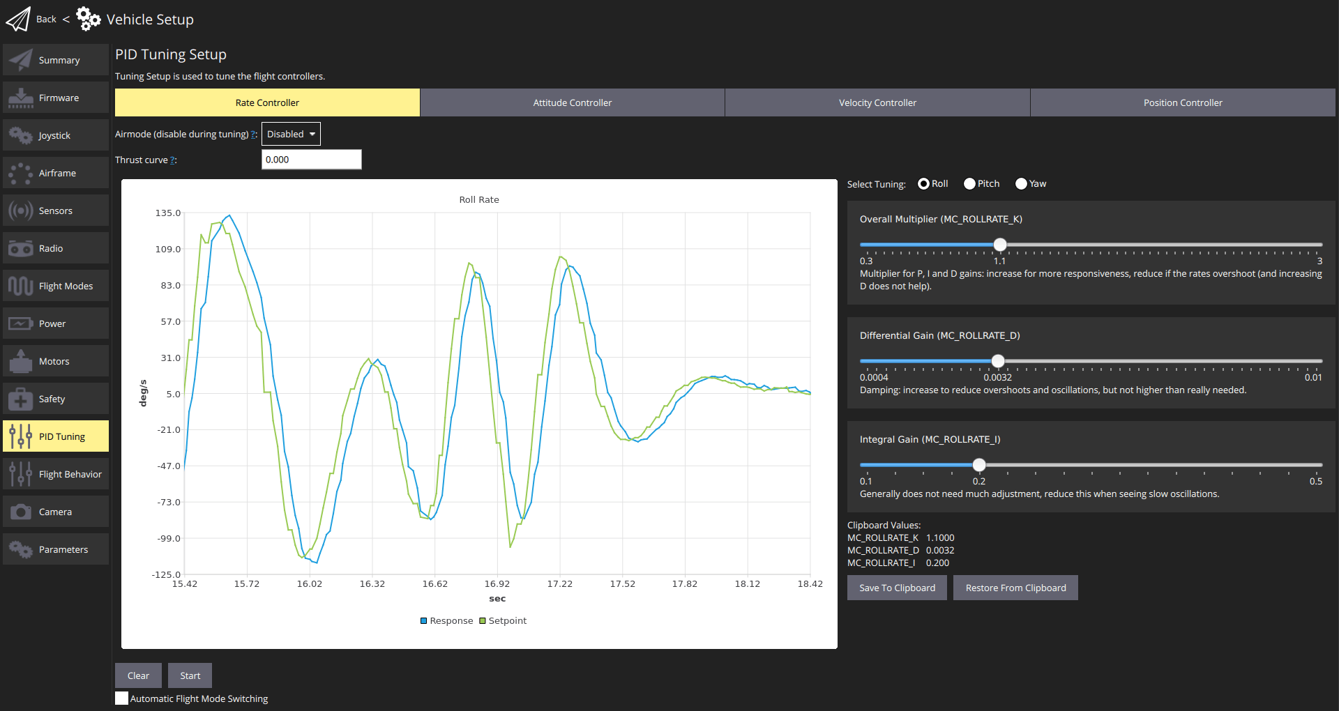
Increase the roll and pitch feed forward gains MC_ROLLRATE_FF, MC_PITCHRATE_FF until the response reaches the setpoint when giving a step input.
Then enable the PID gains. Start off with following values:
- MC_ROLLRATE_P, MC_PITCHRATE_P a quarter of the value you found to work well as the corresponding feed forward value in the previous step.
P = FF / 4
shparam set MC_ROLLRATE_I 0.2 param set MC_PITCHRATE_I 0.2 param set MC_ROLLRATE_D 0.001 param set MC_PITCHRATE_D 0.001Then increase the
PandDgains as needed until it tracks well. It is expected that thePgain is considerably smaller than theFFgain.- MC_ROLLRATE_P, MC_PITCHRATE_P a quarter of the value you found to work well as the corresponding feed forward value in the previous step.