Velocity Tuning
WARNING
The attitude tuning must've already been completed before this step!
INFO
To tune we will be using the manual Position mode. This mode requires a global position estimate (GPS) and tuning of some parameters that go beyond the velocity controller. If you use a custom external flight mode that controls velocity but does not require a global position estimate you can ignore the manual position mode parameters.
Speed Parameters
To tune the velocity controller configure the following parameters in QGroundControl:
RO_SPEED_LIM [m/s]: This is the maximum speed you want to allow for your rover. This will define the stick-to-speed mapping for Position mode and set an upper limit for the speed setpoint.
RO_MAX_THR_SPEED [m/s]: This parameter is used to calculate the feed-forward term of the closed loop speed control which linearly maps desired speeds to normalized motor commands. As mentioned in the Manual mode configuration , a good starting point is the observed ground speed when the rover drives at maximum throttle in Manual mode.
TIP
To further tune this parameter:
- Set RO_SPEED_P and RO_SPEED_I to zero. This way the speed is only controlled by the feed-forward term, which makes it easier to tune.
- Put the rover in Position mode and then move the left stick of your controller up and/or down and hold it at a few different levels for a couple of seconds each.
- Disarm the rover and from the flight log plot the
adjusted_speed_body_x_setpointand themeasured_speed_body_xfrom the RoverSpeedStatus message over each other. - If the actual speed of the rover is higher than the speed setpoint, increase RO_MAX_THR_SPEED. If it is the other way around decrease the parameter and repeat until you are satisfied with the setpoint tracking.
INFO
If your rover oscillates when driving a straight line in Position mode, set this parameter to the observed ground speed at maximum throttle in Manual mode and complete the tuning of the manual position mode parameters first before continuing the tuning of the closed loop speed control.
RO_SPEED_P [-]: Proportional gain of the closed loop speed controller.
TIP
This parameter can be tuned the same way as RO_MAX_THR_SPEED. If you tuned RO_MAX_THR_SPEED well, you might only need a very small value.
RO_SPEED_I [-]: Integral gain for the closed loop speed controller.
TIP
For the closed loop speed control an integrator gain is useful because this setpoint is often constant for a while and an integrator eliminates steady state errors that can cause the rover to never reach the setpoint.
(Advanced) RO_SPEED_TH [m/s]: The minimum threshold for the speed measurement not to be interpreted as zero. This can be used to cut off measurement noise when the rover is standing still.
Manual Position Mode Parameters
These steps are only necessary if you are tuning/want to unlock the manual Position mode. Otherwise, you can continue with position tuning where these same parameters will also be configured.
PP_LOOKAHD_GAIN: When driving in a straight line (right stick centered) position mode leverages the same path following algorithm used in auto modes called pure pursuit to achieve the best possible straight line driving behaviour. This parameter determines how aggressive the controller will steer towards the path.
TIP
Decreasing the parameter makes it more aggressive but can lead to oscillations.
To tune this:
- Start with a value of 1 for PP_LOOKAHD_GAIN
- Put the rover in Position mode and while driving a straight line at approximately half the maximum speed observe its behaviour.
- If the rover does not drive in a straight line, reduce the value of the parameter, if it oscillates around the path increase the value.
- Repeat until you are satisfied with the behaviour.
PP_LOOKAHD_MIN: Minimum threshold for the lookahead distance used by the pure pursuit algorithm.
TIP
Put the rover in Position mode and drive at very low speeds, if the rover starts to oscillate even though the tuning of PP_LOOKAHD_GAIN was good for medium speeds, then increase the value of PP_LOOKAHD_MIN.
PP_LOOKAHD_MAX: Maximum threshold for the lookahead distance used by pure pursuit.
TIP
Put the rover in Position mode and drive at very high speeds, if the rover does not drive in a straight line even though the tuning of PP_LOOKAHD_GAIN was good for medium speeds, then decrease the value of PP_LOOKAHD_MAX.
The rover is now ready to drive in Position mode and the configuration can be continued with position tuning.
Velocity Controller Structure (Info Only)
This section provides additional information for developers and people with experience in control system design.
The velocity vector is defined by the following two values:
- The absolute speed [
] - The direction (bearing) [
]
The speed controller uses the following structure:
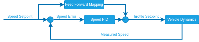
The feed forward mapping is done by interpolating the speed setpoint from [-RO_MAX_THR_SPEED, RO_MAX_THR_SPEED] to [-1, 1].
For ackermann and differential rovers the bearing is aligned with the vehicle yaw. Therefore the bearing is simply sent as a yaw setpoint to the yaw controller and the speed setpoint is always defined in body x direction.
For mecanum vehicles, the bearing and yaw are decoupled. The direction is controlled by splitting the velocity vector into one speed component in body x direction and one in body y direction. Both these setpoint are then sent to their own closed loop speed controllers.
Parameter Overview
| Parameter | Description | Unit |
|---|---|---|
| RO_MAX_THR_SPEED | Speed the rover drives at maximum throttle | |
| RO_SPEED_LIM | Maximum allowed speed | |
| RO_SPEED_P | Proportional gain for speed controller | - |
| RO_SPEED_I | Integral gain for speed controller | - |
| RO_SPEED_TH | (Advanced) Speed measurement threshold |
Pure Pursuit
| Parameter | Description | Unit |
|---|---|---|
| PP_LOOKAHD_GAIN | Pure pursuit: Main tuning parameter | - |
| PP_LOOKAHD_MAX | Pure pursuit: Maximum value for the look ahead radius | m |
| PP_LOOKAHD_MIN | Pure pursuit: Minimum value for the look ahead radius | m |