RPi PilotPi Shield
WARNING
PX4 does not manufacture this (or any) autopilot. Contact the manufacturer for hardware support or compliance issues.
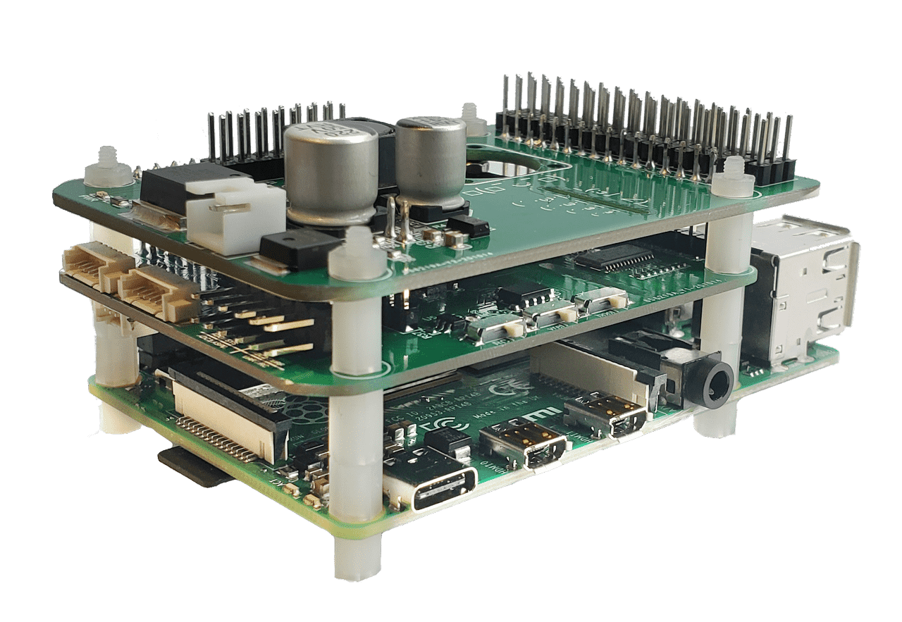
The PilotPi shield is a fully functional solution to run PX4 autopilot directly on Raspberry Pi. It is designed to be a low-cost but highly scalability platform with continuous updates from both Linux and PX4 sides. No proprietary driver is required, as all components have upstream support from RPi and PX4 community. PCB and schematic are open source as well.
Quick Summary
- Supported RPi boards:
- Raspberry Pi 2B/3B/3B+/4B
- Supported OS:
- Raspberry Pi OS
- Ubuntu Server (armhf/arm64)
- Accelerometer / Gyro:
- ICM42688P
- Magnetometer:
- IST8310
- Barometer:
- MS5611
- PWM:
- PCA9685
- ADC:
- ADS1115
- Power:
- 3~6S battery with built-in voltage sensing.
- Power the Pi through USB cable
- Availability: preparing for shipping
Connectivity
Shield provides:
- 16x PWM outputting channels
- GPS connector
- Telemetry connector
- External I2C bus connector (Note: conflicts with CSI camera)
- RC input port (SBUS)
- 3x ADC channels range 0~5V
- 2*8 2.54mm unused GPIO connector
Direct accessible from RPi:
- 4x USB connector
- CSI connector(Note: conflict with external I2C bus)
- etc.
Recommended Wiring
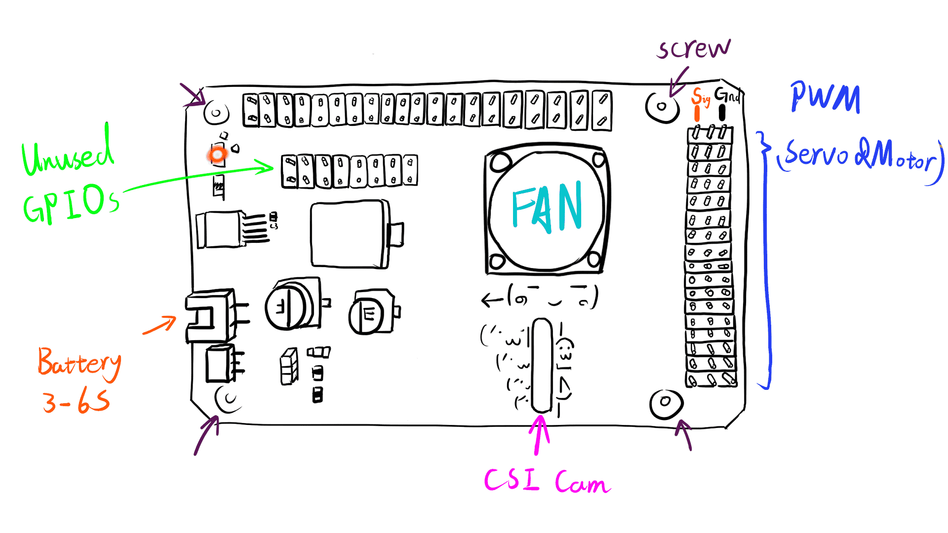
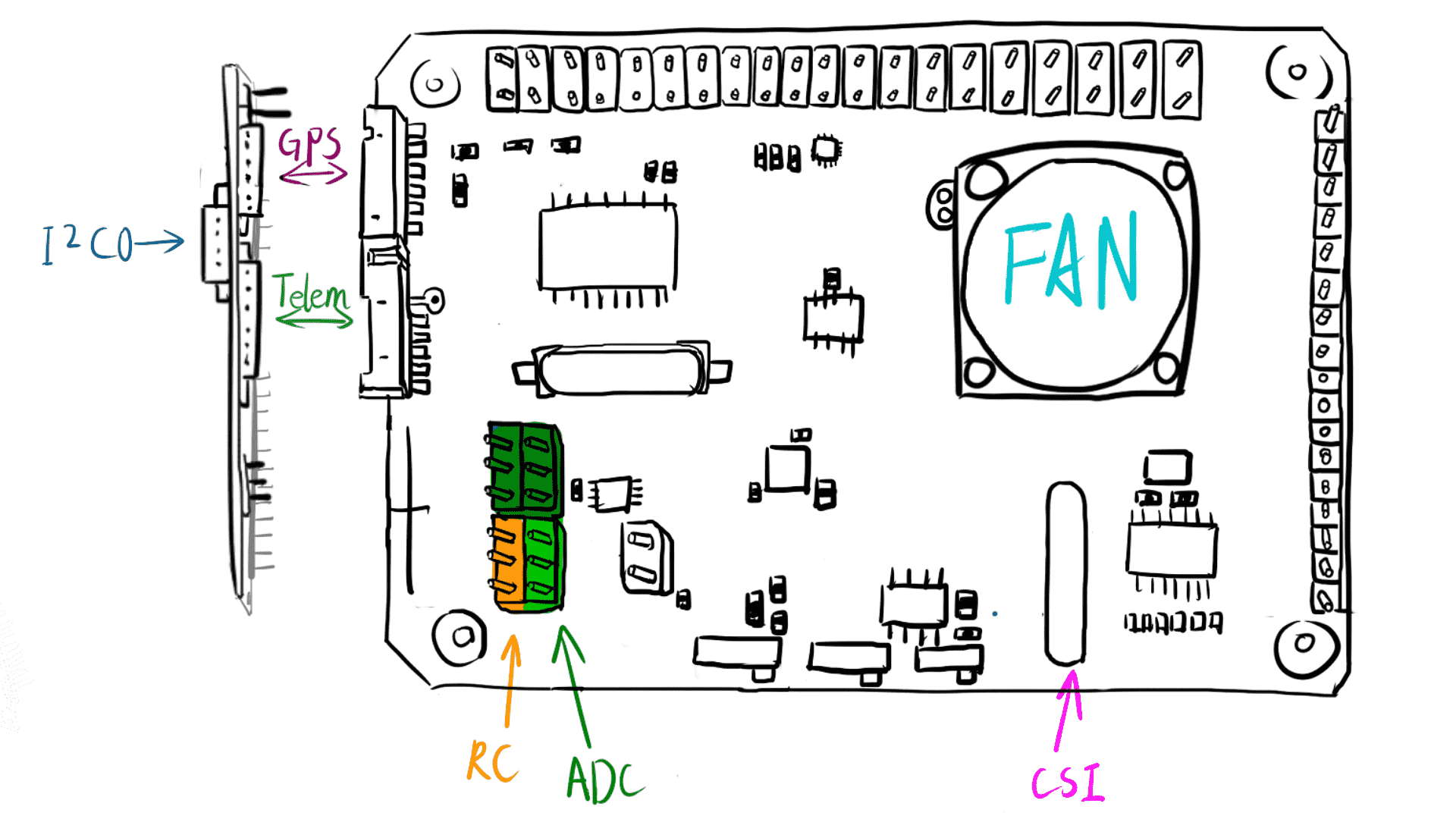
Pinout
WARNING
It still uses old GH1.25 connectors. Wiring is compatible with Pixhawk 2.4.8
Connectors
GPS connector
Mapped to /dev/ttySC0
| Pin | Signal | Volt |
|---|---|---|
| 1 | VCC | +5V |
| 2 | TX | +3v3 |
| 3 | RX | +3v3 |
| 4 | NC | +3v3 |
| 5 | NC | +3v3 |
| 6 | GND | GND |
Telemetry connector
Mapped to /dev/ttySC1
| Pin | Signal | Volt |
|---|---|---|
| 1 | VCC | +5V |
| 2 | TX | +3v3 |
| 3 | RX | +3v3 |
| 4 | CTS | +3v3 |
| 5 | RTS | +3v3 |
| 6 | GND | GND |
External I2C connector
Mapped to /dev/i2c-0
| Pin | Signal | Volt |
|---|---|---|
| 1 | VCC | +5V |
| 2 | SCL | +3v3(pullups) |
| 3 | SDA | +3v3(pullups) |
| 4 | GND | GND |
RC & ADC2/3/4
RC is mapped to /dev/ttyAMA0 with signal inverter switch on RX line.
| Pin | Signal | Volt |
|---|---|---|
| 1 | RC | +3V3~+5V |
| 2 | VCC | +5V |
| 3 | GND | GND |
- ADC1 is internally connected to voltage divider for battery voltage monitoring.
- ADC2 is left unused.
- ADC3 can be connected to an analog airspeed sensor.
- ADC4 has a jumper cap between ADC and VCC, to monitor system voltage level.
| Pin | Signal | Volt |
|---|---|---|
| 1 | ADCx | 0V~+5V |
| 2 | VCC | +5V |
| 3 | GND | GND |
INFO
ADC3 & 4 have an alternative VCC source When 'Vref' switch is on, 'VCC' pin is driven by REF5050.
Unused GPIO available on top of the board
| Shield Pin | BCM | WiringPi | RPi Pin |
|---|---|---|---|
| 1 | 3V3 | 3v3 | 3V3 |
| 2 | 5V | 5V | 5V |
| 3 | 4 | 7 | 7 |
| 4 | 14 | 15 | 8 |
| 5 | 17 | 0 | 11 |
| 6 | 27 | 2 | 13 |
| 7 | 22 | 3 | 15 |
| 8 | 23 | 4 | 16 |
| 9 | 7 | 11 | 26 |
| 10 | 5 | 21 | 29 |
| 11 | 6 | 22 | 31 |
| 12 | 12 | 26 | 32 |
| 13 | 13 | 23 | 33 |
| 14 | 16 | 27 | 36 |
| 15 | 26 | 25 | 37 |
| 16 | GND | GND | GND |
Switches
RC Inverter
This switch will decide the signal polarity of RX line: UART_RX = SW xor RC_INPUT
- On: suitable with SBUS (signal inverted)
- Off: preserved
Vref
ADC 3 & 4 will have VCC driven by:
- Vref output from REF5050 if on
- 5V pin directly from RPi if off
Boot Mode
This switch is connected to Pin22(BCM25). System rc script will check its value and decide whether PX4 should start alongside with system booting or not.
- On: start PX4 automatically
- Off: don't start PX4
Developer Quick Start
Refer to specific instructions for the OS running on your RPi: