J.Fi Wireless Telemetry Module
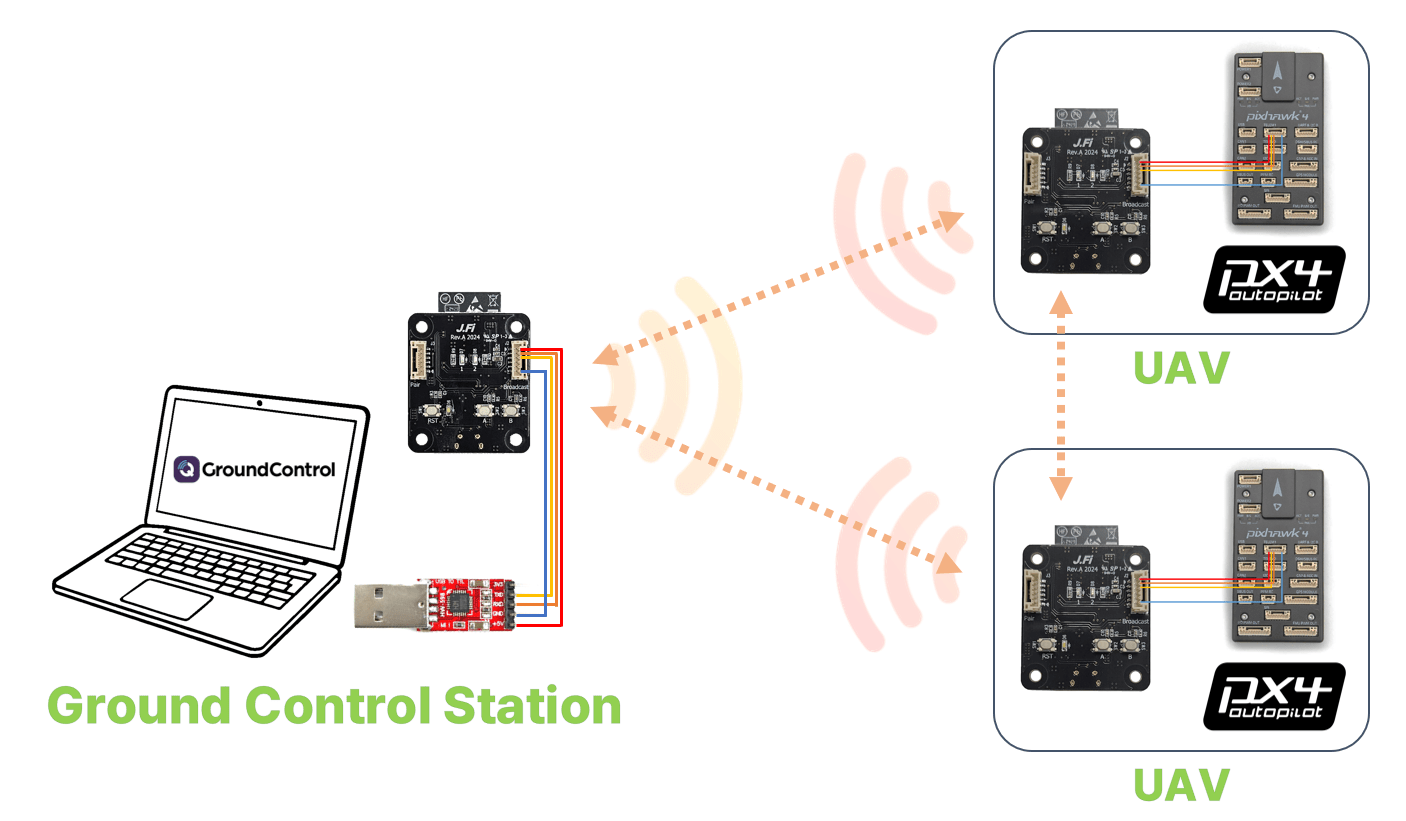
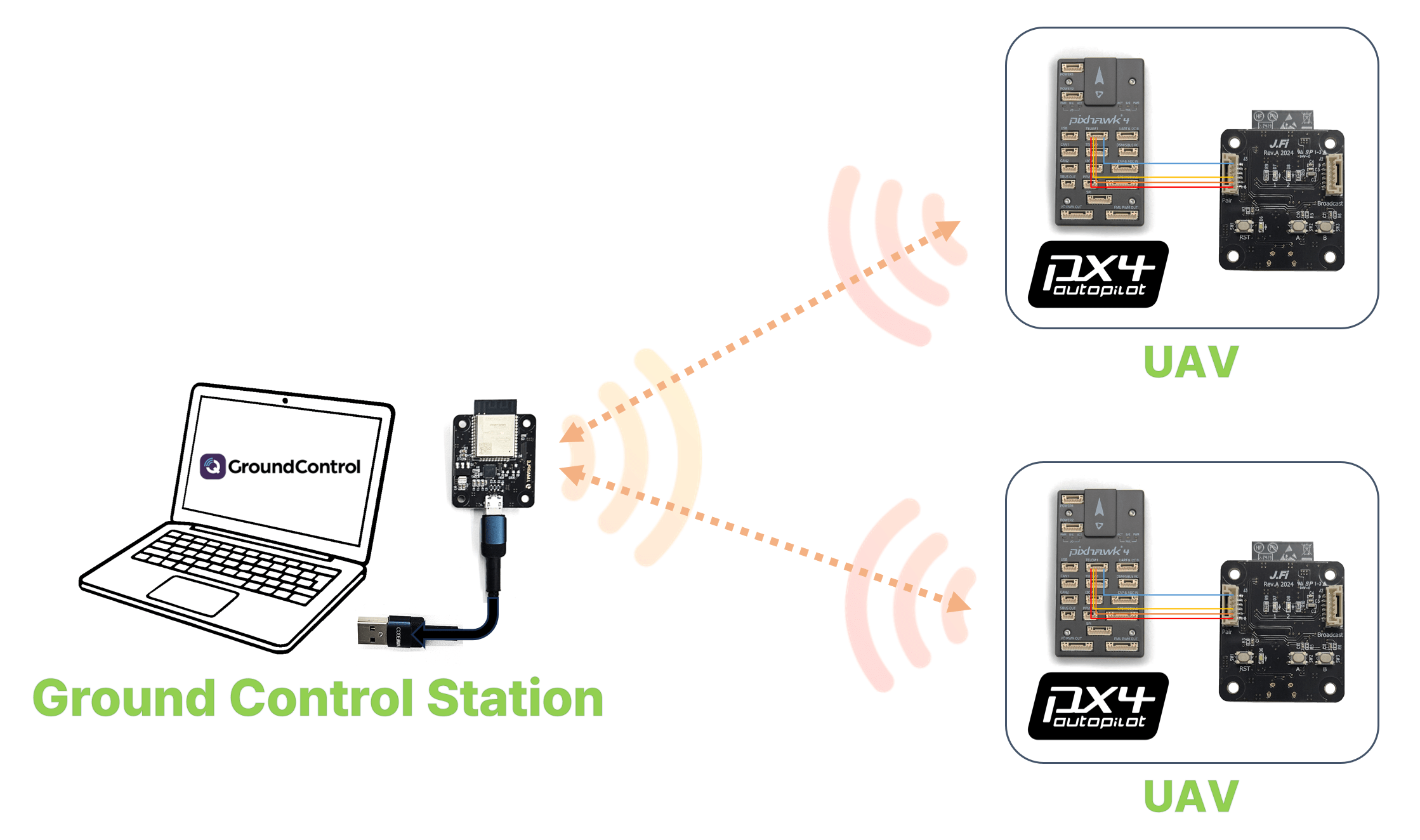
The J.MARPLE J.Fi telemetry module is a compact and lightweight wireless communication device featuring a PCB-integrated antenna or external antenna, enabling seamless telemetry connections between various drone flight controllers (FC) and ground control stations.
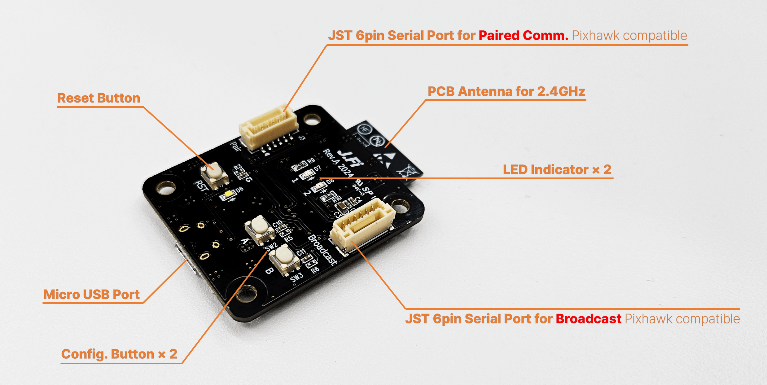
This module includes a Pixhawk-standard JST 6-pin TELEM connector, ensuring compatibility with all PX4-based flight controllers. It supports quick plug-and-play operation to TELEM1 with default settings, requiring no additional configuration.
The J.Fi telemetry module provides reliable communication up to approximately 500 meters when using a PCB-integrated antenna. Operating in the 2.4GHz frequency band, it allows unrestricted global use without regulatory limitations.
Where to Buy
Technical Specifications
Wireless Performance
- Frequency Band: 2.4GHz
- Speed: Up to 11 Mbps (adjustable)
- Range: Up to 1000 meters (varies upon environments)
- Payload Capacity: Up to 1024 bytes
Network Schemes
- Supported Topologies: 1:1, 1:N, N:N
- Collision Management: Time Slot-Based Response Delay
User-Friendly Features
- Buttons: Pairing and Mode Switching
- LED Indicators: Real-time status updates
- Configuration: Web browser-based setup
- Micro USB Port for connecting to PC or GCS
Broadcast Communication
With default settings enabled, the device automatically broadcasts data to all nearby J.Fi devices. Connect your external device or system to the Broadcast port. No additional setup is required.
Paired Communication
- Modules must first undergo an initial pairing procedure.
- Once paired, communication is restricted to paired J.Fi devices. Connect your external device or system to the Pair port.
1:1 Pairing
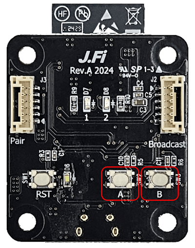
- On each device, press and hold button A, then click the RST button. Release button A when LED 1 blinks.
- Both devices will enter pairing mode
- Choose one module and double-click button A
- On the other module, click button A once
- On the first module, click button A once again to finish pairing
- Pairing complete
1:N Pairing
- On each device, press and hold button A, then click the RST button. Release button A when LED 1 blinks.
- All devices will enter pairing mode
- Host module (1): Double-click button A
- Client modules (N): Click button A once on each module to pair
- Host module (1): Click button A again to finish pairing
- Pairing complete.
PX4 Setup
PX4 is plug-and-play with J.Fi if connected to the TELEM1 port, and should connect without further connection.
If you want to use another port you will need to assign a MAVLink instance to the serial port (see MAVLink Peripherals (GCS/OSD/Companion)) (and possibly unassign whatever is currently using the port).
One-to-one (1:1) Setups
The TELEM1 port is set to use 57600 as the baud rate by default (and J.Fi is set to match). This default baud rate is calibrated for inexpensive low-power telemetry radios. While this should be sufficient for 1:1 setups, J.Fi will work with much higher rates (i.e., 115200).
If you want to change the baud rate:
- Change SER_TEL1_BAUD if you're using the
TELEM1port (see Serial Port Configuration for other ports). - Update the baud rate in the J.Fi Configuration to match.
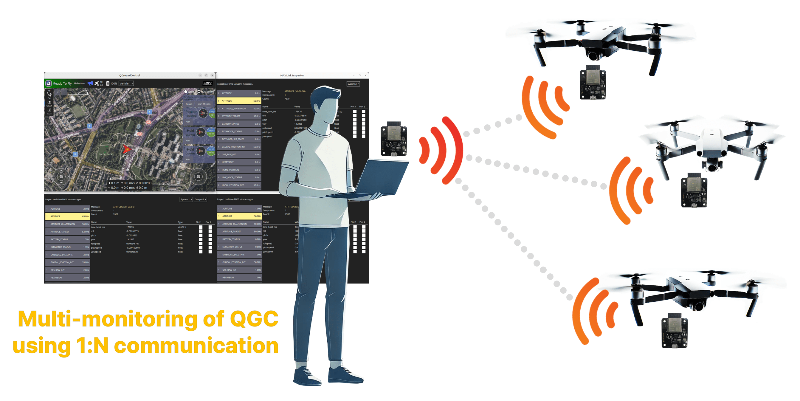
One-to-many (1:N) Setups
For one-to-many (1:N) setups a higher baud rate is highly recommended to ensure stable data reception. All J.Fi devices should be set to the same baud rate (although communication may work even when devices use different baud rates). This should be changed in both PX4 and the J.Fi modules as explained in the previous section.
You will also need to make sure that all vehicles on the MAVLink network are assigned a unique System ID (MAV_SYS_ID).
QGroundControl Configuration
The J.Fi will connect plug-and-play to QGroundControl and automatically connect just like a SiK Radio.
However if you change the baud rate from 57600 you will need to create and use a new link configuration:
- Disable SiK Radio in QGC (Application Settings → General → AutoConnect).
- Create a new link configuration:
- Go to Application Settings → Comms Links.
- Click Add.
- Set Type to Serial, configure the Serial Port and Baud Rate to match the J.Fi device.
- Select Connect to connect with the new configuration.
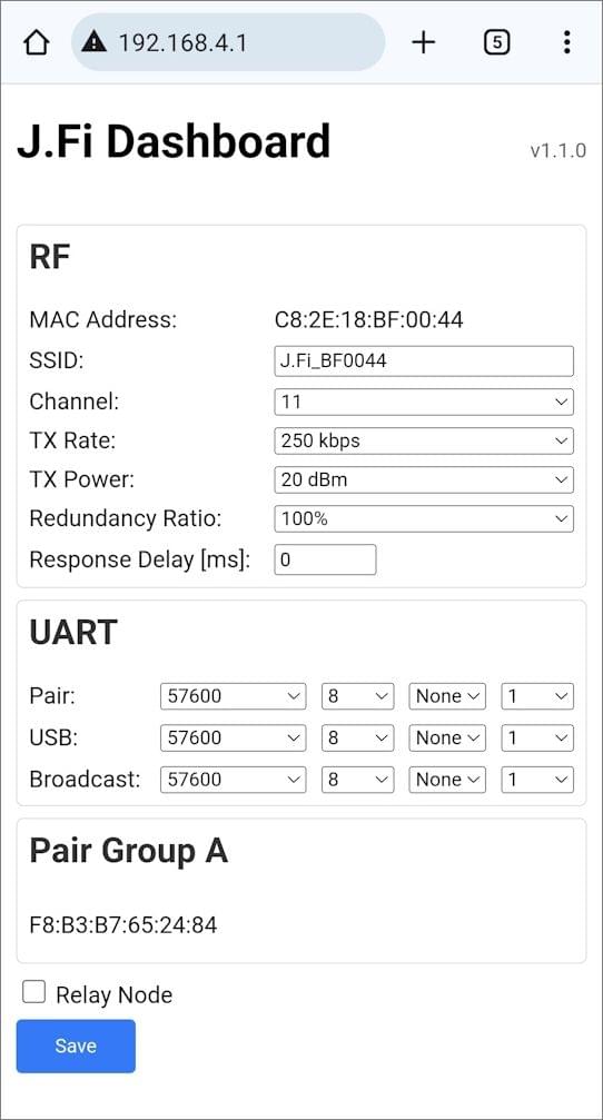
J.Fi Configuration
- Device: Press and hold button B, then click the RST button. Release button B when LED 2 blinks.
- Device enters configuration mode
- Smart device: Connect to Wi-Fi network named
J.Fi-xxxxxx(x: alphanumeric characters) - Browser: Go to
192.168.4.1to open the configuration page. - Configuration page: Adjust settings as needed, then click Save
- LED 2 blinks once upon saving