Reptile Dragon 2 (RD2) Build
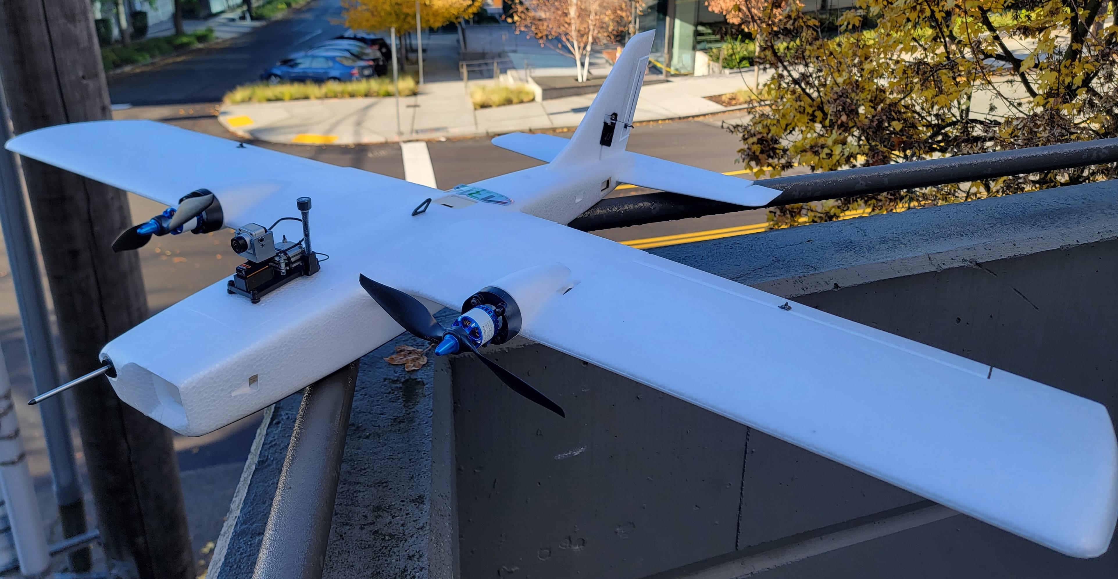
The Reptile Dragon 2 is a twin motor RC airplane specifically designed for efficient FPV (first person view) flying. Being specific for FPV, the RD2 is optimized for easy mounting of cameras, sensors, logic electronics, large batteries, antennas, and other payload components which would be found on a typical FPV airplane. This emphasis on payload makes this airplane an ideal candidate for a PX4 installation.
Overview
The goal of this build was to create an efficient, long endurance FPV platform to be used for general PX4 testing and development.
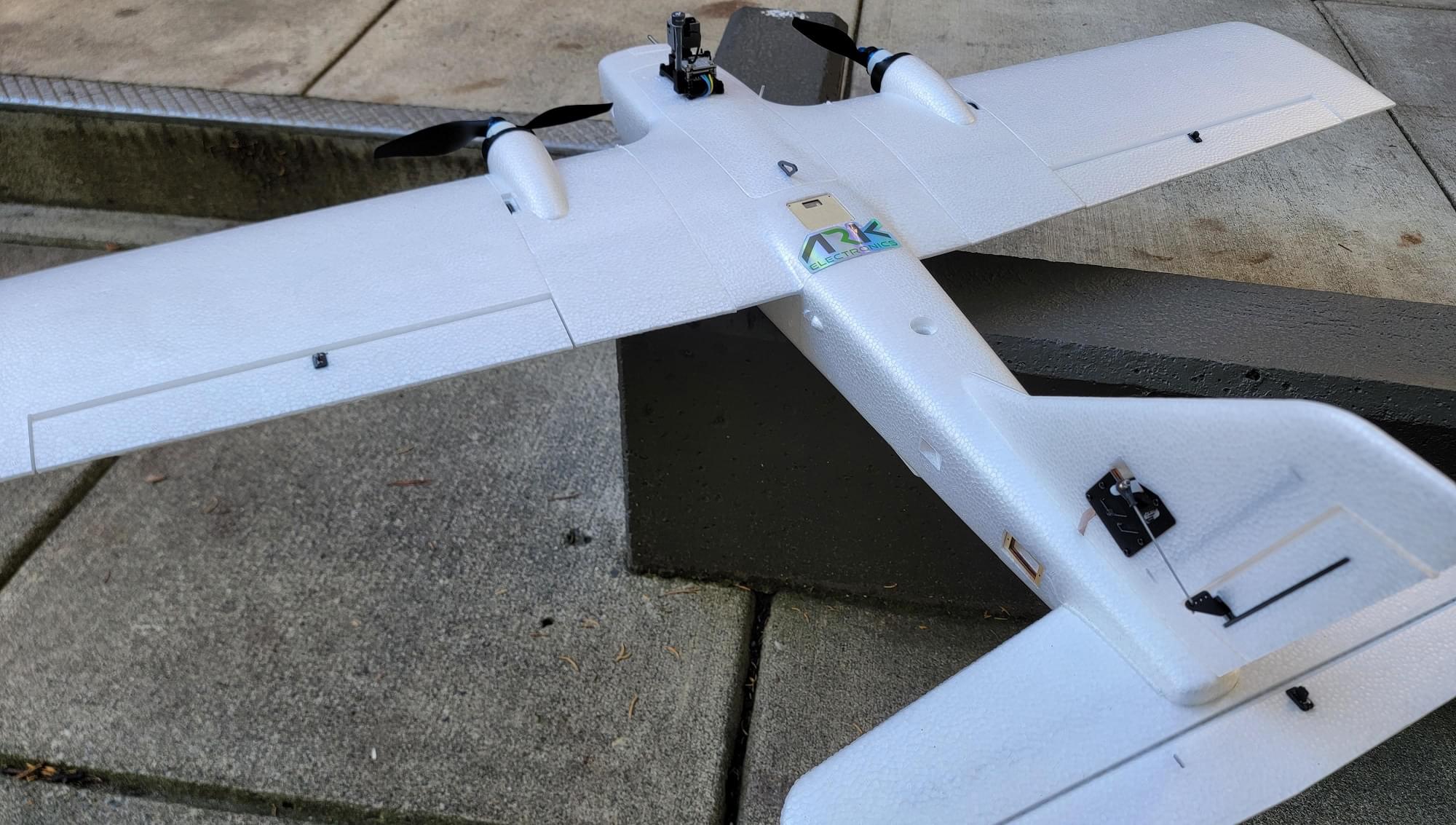
Key airframe features:
- Spacious interior
- Easy access to the entire fuselage cavity with large top hatch
- Rear hatch
- Removable V tail or conventional tail options included
- Threaded inserts in the wings and fuselage top for external mounting
- Numerous mounting features
- Top antenna hole
- Top GPS cover
- Side "T" antenna mounts
- Rear electronics tray
- Front facing "action cam" cutout
- Front facing FPV camera cutout
- Removable wings
- Low stall speed
- Gentle handling
Key build features
- Easy overall build
- Easy access to Pixhawk and all peripherals
- FPV with camera pan mount
- Air data from pitot/static probe
- ~40 minute long flight times
Parts list
Holybro PWM breakout board
MS4525DO differential pressure module and pitot tube
6s2p 18650 LiIon flight battery (select XT60 connector)
Custom designed 3D printed parts
- ARK6X carrier mount
- Holybro Pixhawk 5x carrier mount
- FPV pod and camera mount
- Pitot static probe "plug" adapter
Misc hardware: M3 hardware (standoffs, washers, O-rings, bolts), M2.5 nylon standoffs and screws, XT30 connectors, hot glue, heatshrink, Molex Microfit connectors
Silicone wiring (14awg for high current, 16awg for low current, 22awg for low power and signals)
Tools
The following tools were used in this assembly.
- Servo tester (with centering button)
- Screw driver set
- 3D printer
- Wrench set
- Glue: Hot glue, CA (Cyanoacrylate) glue, "Foamtac" glue
- Sandpaper
Airframe Build
The airplane needs some assembly out of the box. Servos, wings, and the tail will need to be installed.
INFO
For this portion of assembly, the instructions included with the kit should be sufficient, but some helpful tips are listed below.
Gluing Foam
When gluing foam parts of the RD2 together, use sandpaper to rough the mating surface, then use CA glue. If the foam is not roughed with sandpaper, the glue will not have a surface to be able to "grab" the foam and the bond will be poor.
Foamtac doesn't seem to stick well to this foam, so I used CA glue for all foam-to-foam mates.
Skid Plate
The skid plate that comes with the RD2 needs to be trimmed to fit.
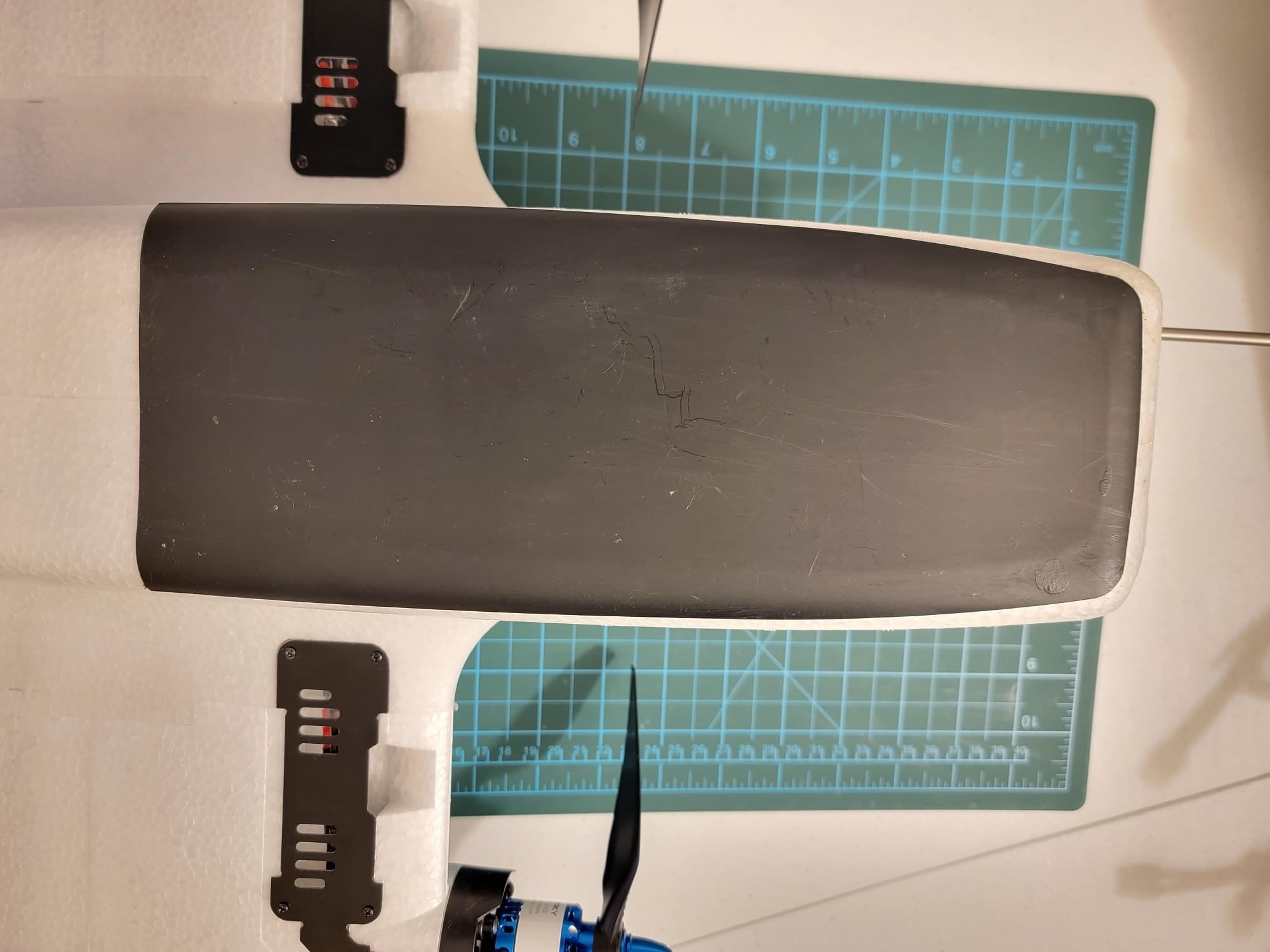
Trim off the mold flashing from the flat side of the skid plate. Use coarse sandpaper to rough the inside surface of the skid plate as well as the mating surface on the underside of the airframe. After checking for fit, use CA glue to glue the skid plate to the bottom of the RD2.
Servo Installation
INFO
Prior to servo installation, it is recommended to use the sandpaper to rough the side of the servo facing the servo cover. During final installation, put a drop of Foamtac between the servo and the cover. This will prevent the servo from moving once installed.
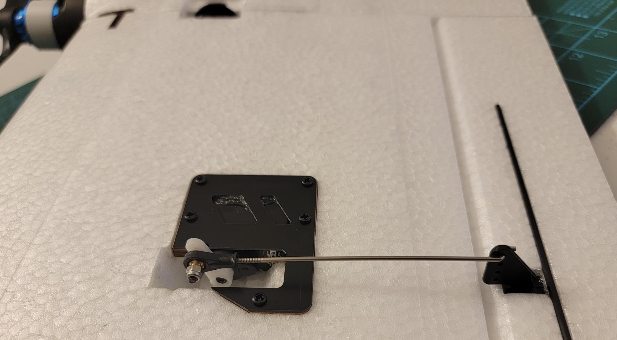
The servos on the RD2 are connected to control surfaces with adjustable servo linkages. The RD2 instructions will note that each control surface uses a specific length of linkage (included in the kit). Make sure to measure each linkage before installation to be sure that it is the right length linkage for that control surface. It's very important to align the servos such that the mechanical range of the servo is well aligned with the mechanical range of the control surface. When the servo is at it's center point, the servo arm should be at a 90 degree angle to the servo, and the control surface should be roughly centered. It might not be possible to get this alignment perfect, so any remaining offset will be adjusted out in software.
The following steps can be used to perform servo alignment:
- Begin with the servo outside of the airplane
- Use the servo tester to move the servo to its center point
- Install the servo horn with the included retaining screw, taking care to align the horn to extend as close as possible to 90 degrees out on the correct side of the servo
- Install the servo in the servo pocket on the airplane
- Install the linkage, and twist to adjust it such that the control surface is as close to centered as possible
INFO
The servo horn will likely not sit exactly at a 90 degree angle to the servo due to the teeth on the servo shaft. You can see this in the above example setup image. Just get it close enough to 90 degrees, and the remaining offset will be removed either with the linkage, or later in software.
GPS/Compass Module Mounting
The GPS/Compass should be mounted in the rear electronics shelf included with the RD2. This location is far aft of power wiring (and anything else that might cause magnetic disturbances), which makes for an ideal location for the GPS/compass module
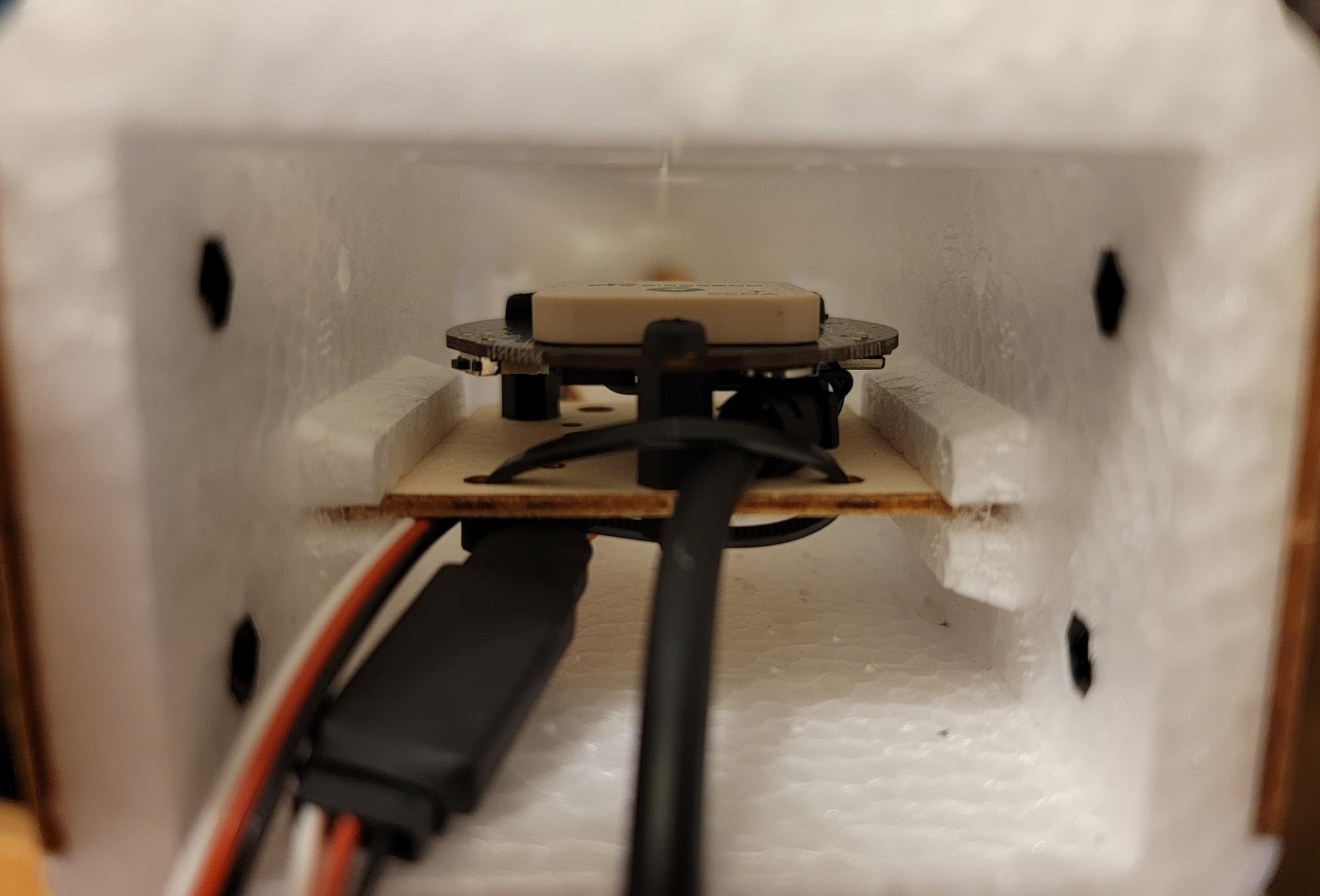
The GPS module can be removed from its plastic case to allow the use of the mounting holes. Then use the nylon M3 hardware to attach it to the rear electronics shelf.
Two of the three required holes are already coincidentally located in the electronics tray, so I used a marker and a drill to mark and drill the third hole.
FPV Pod
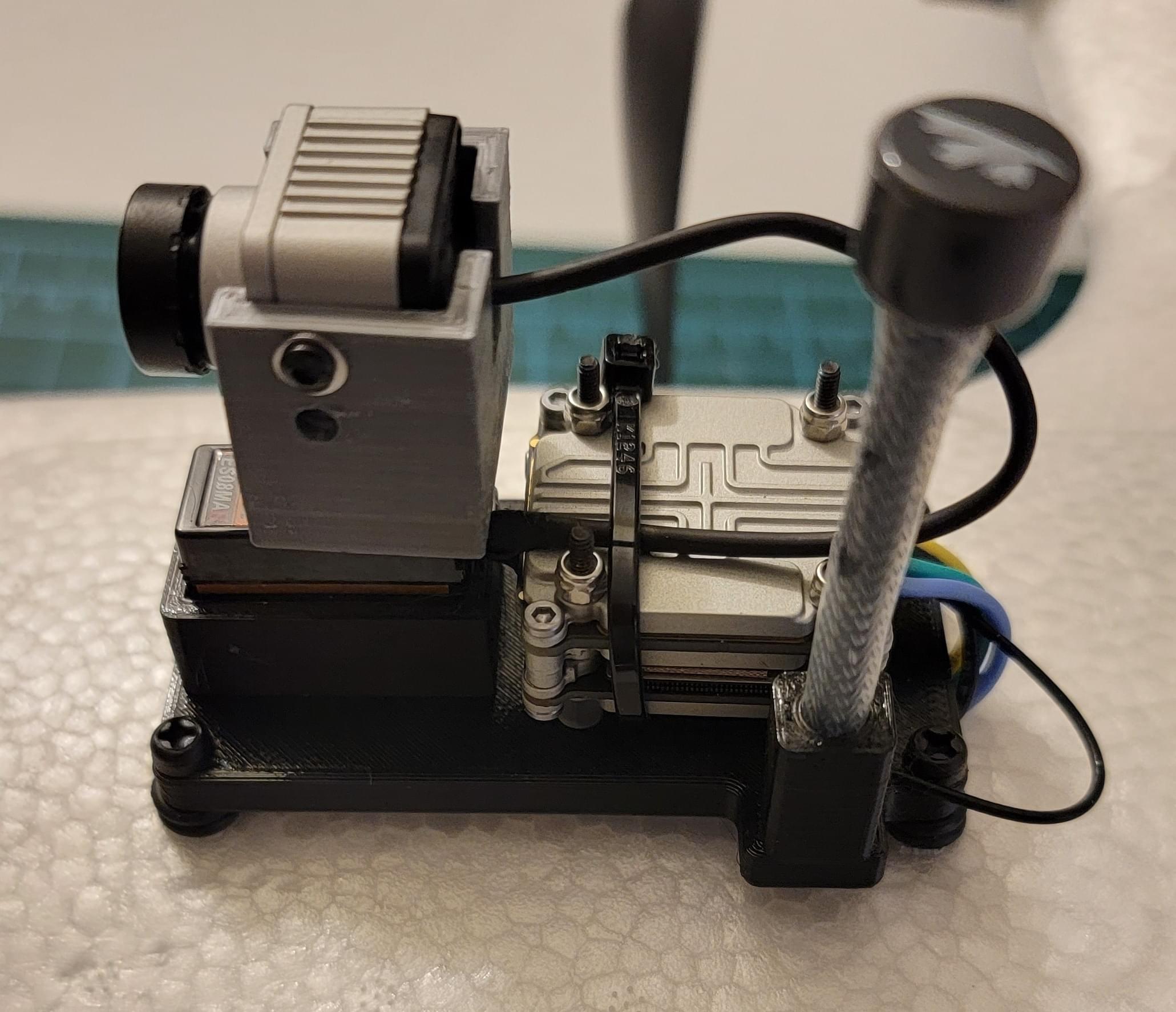
FPV Pod Assembly
First, mount the ES08MA ii servo in the servo pocket of the FPV pod. The servo should simply slip in, with the cable exiting the FPV Pod through the hole in the servo pocket. Use a dot of Foamtac glue to secure the servo.
Use one of the servo horns included in the ES08ma ii package. Cut the horn such that it fits in the slot in the FPV pod camera carrier. It should sit flush to the bottom of the slot. Secure the horn with CA glue.
Use the servo tester to center the servo. Attach the camera carrier servo horn directly to the top of the servo and secure it with the included screw. Secure the DJI FPV camera into the carrier with the two side screws.
To finish the FPV pod assembly, install the Caddx Vista to the back of the pod using long M2 bolts, 1mm standoffs, and nylock nuts.
FPV Pod Airframe Installation
The FPV pod was mounted on top of the battery hatch using nylon M3 bolts with two O-rings to space the FPV pod base plate from the battery hatch.
Flight Computer Installation
INFO
This build is compatible with both the ARK6X carrier and the Holybro 5X Carrier. Instructions are provided for both.
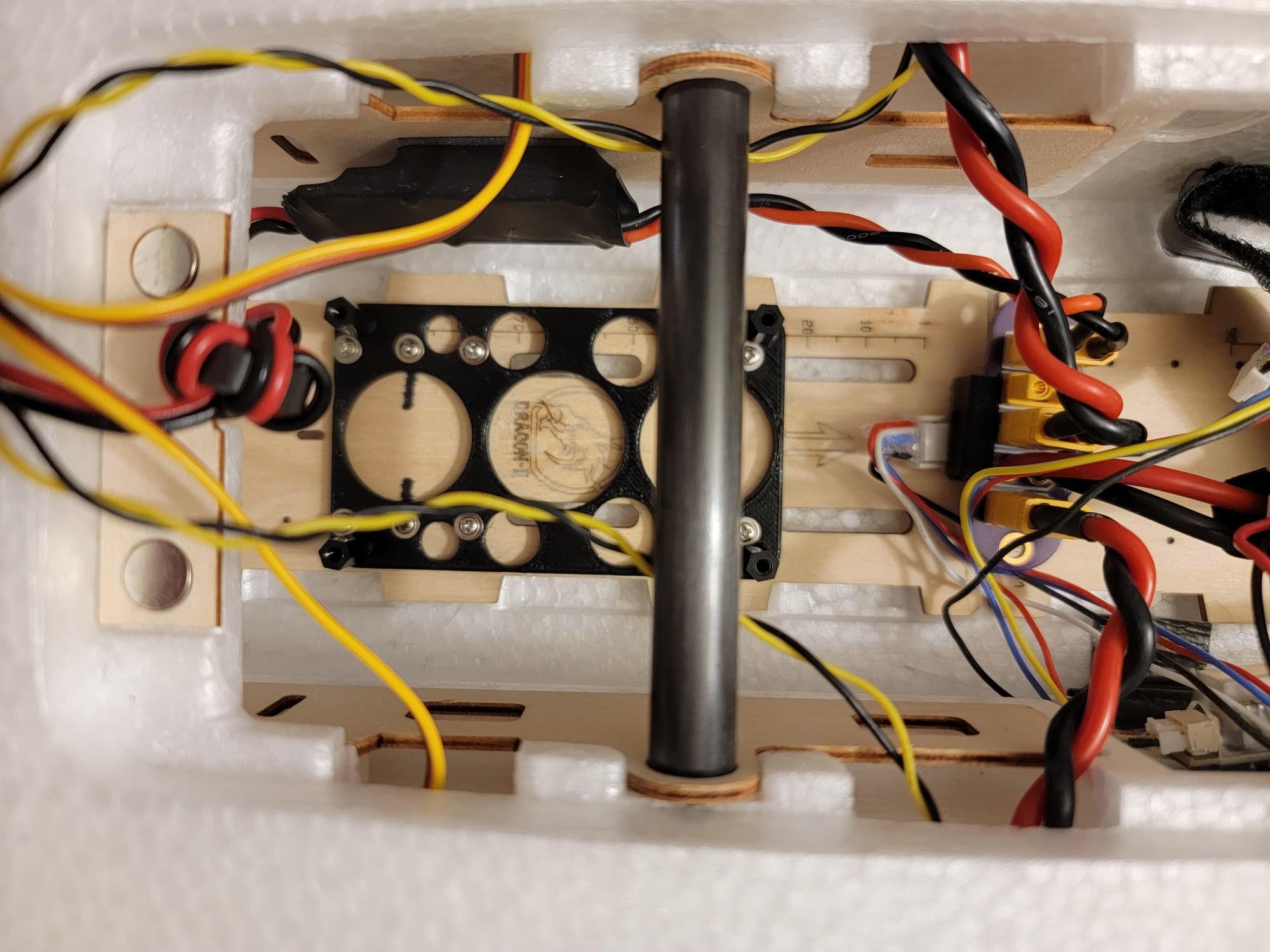
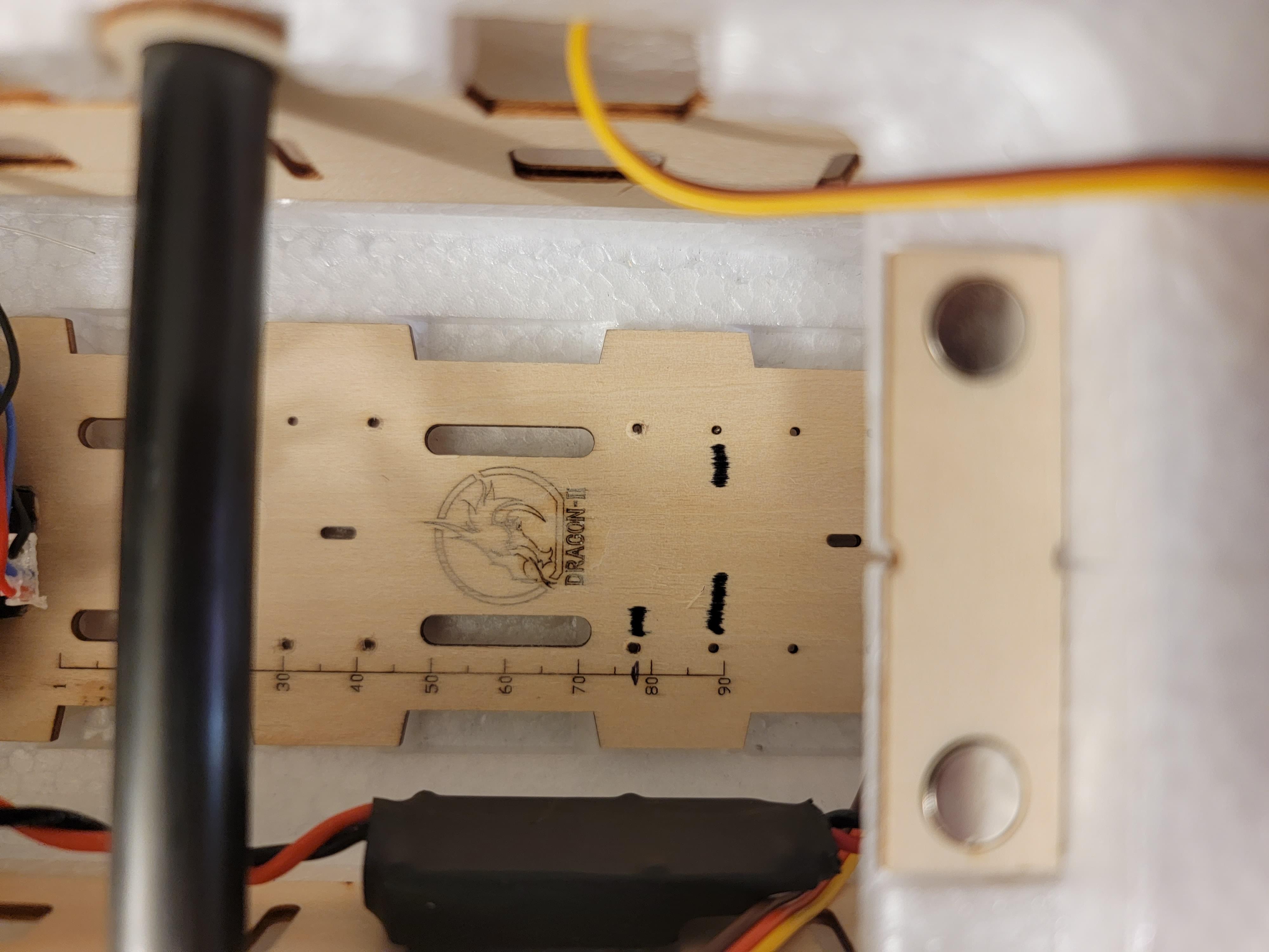 The RD2 comes with a wooden electronics mount baseplate preglued in the airframe. In this image, two sets of marker ticks are used to indicate where the mounts for each carrier mount should back up to; the single tik for the Holybro 5X carrier mount, and the two ticks for the ARK5X carrier mount.
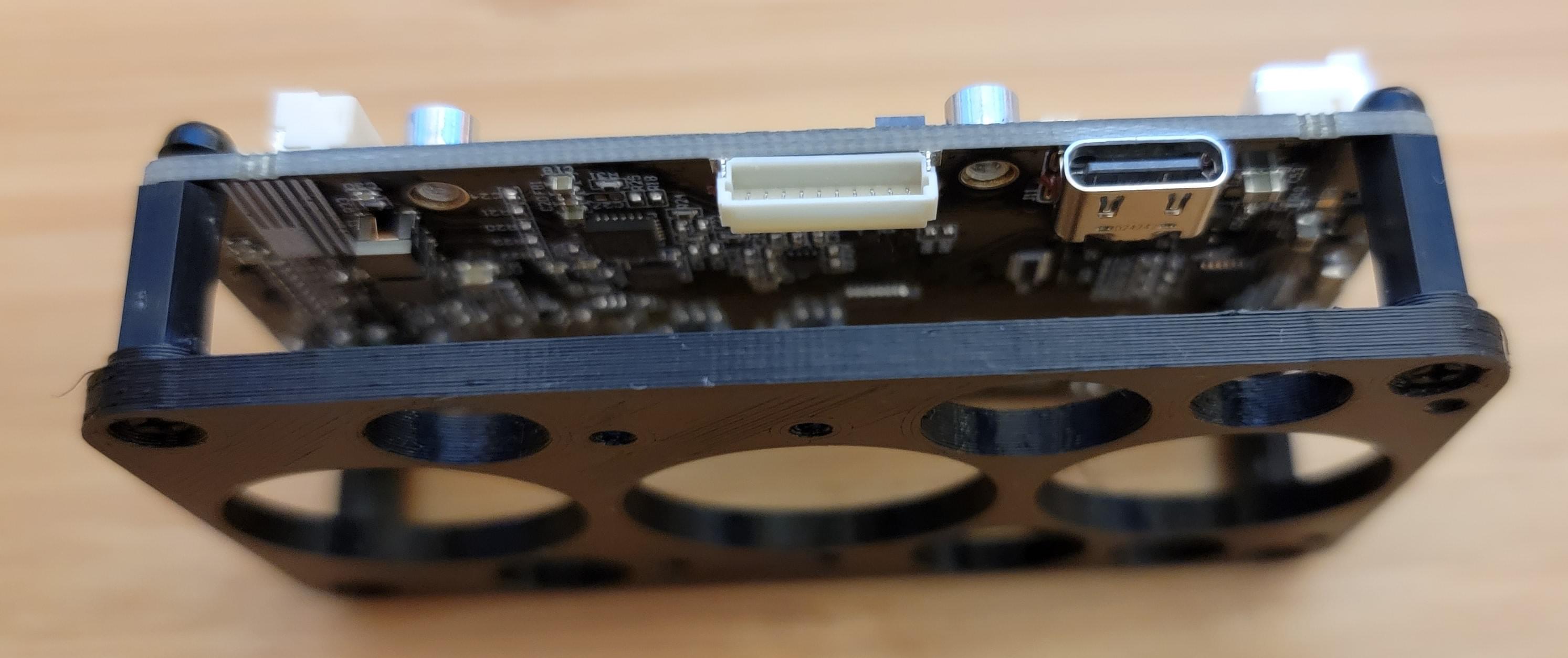
ARK6X Carrier (Recommended)
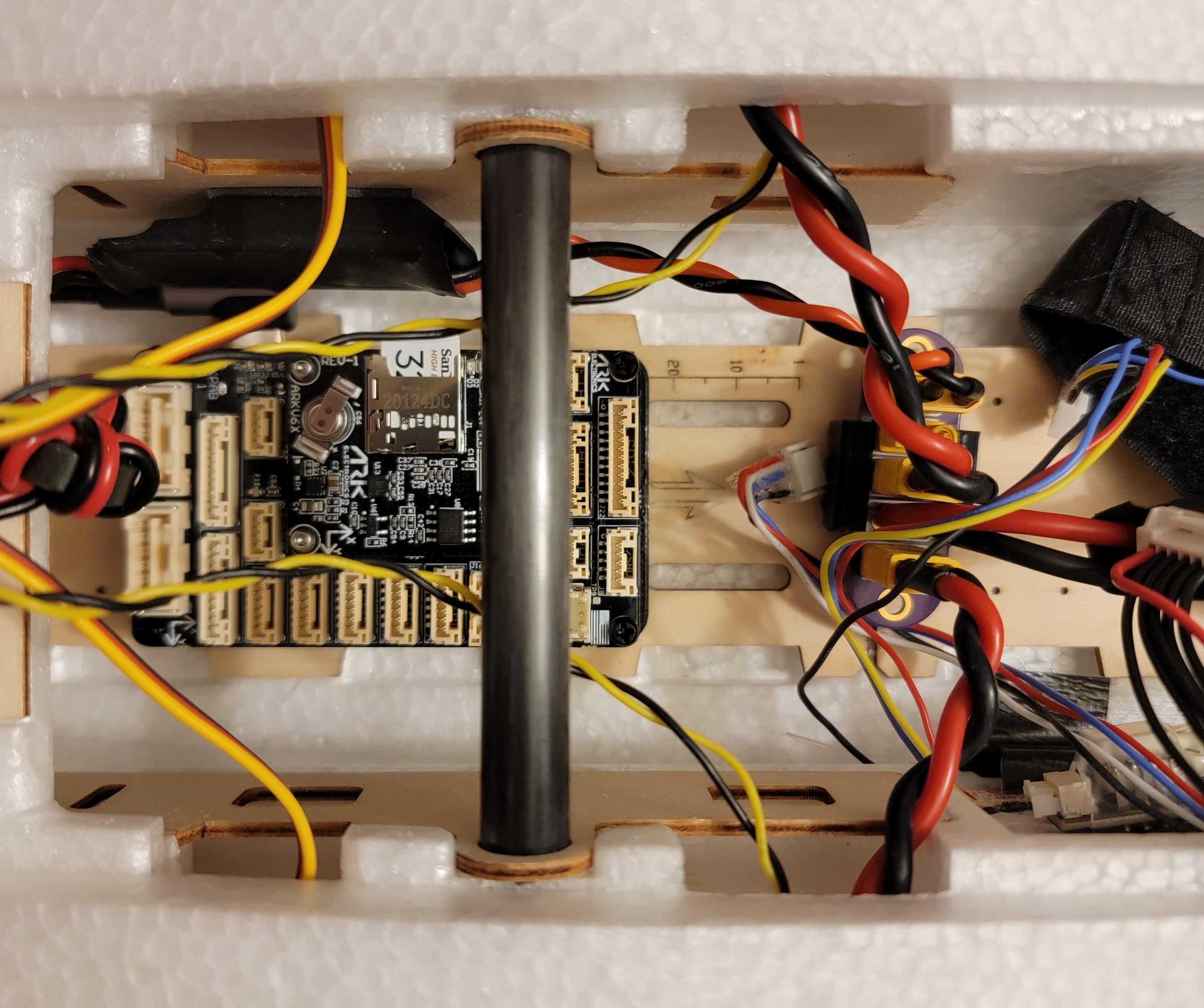
A custom 3D printed mount was made for the ARK6X carrier. M2.5 nylon hardware was used to secure the ARK6X carrier to the mount.
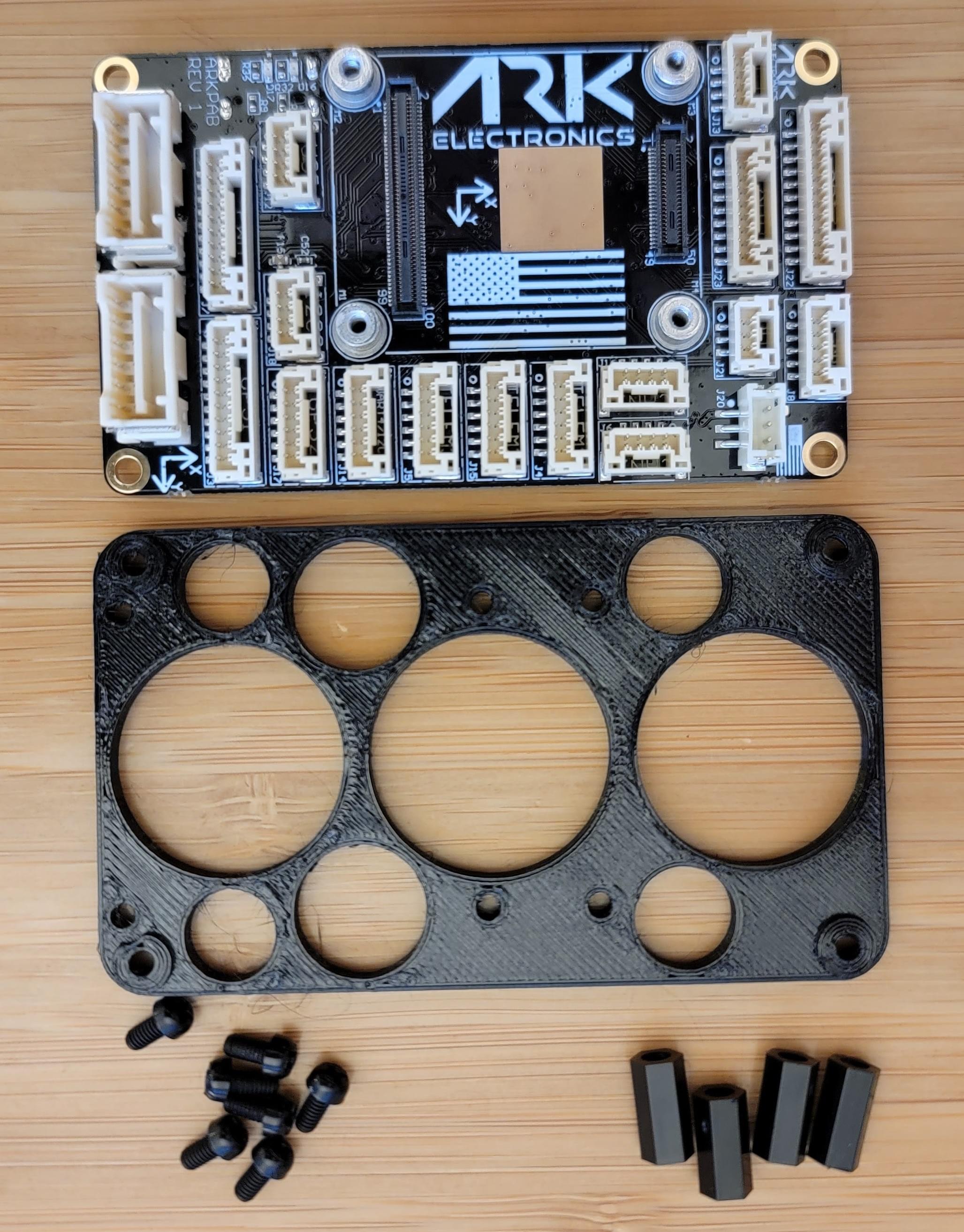
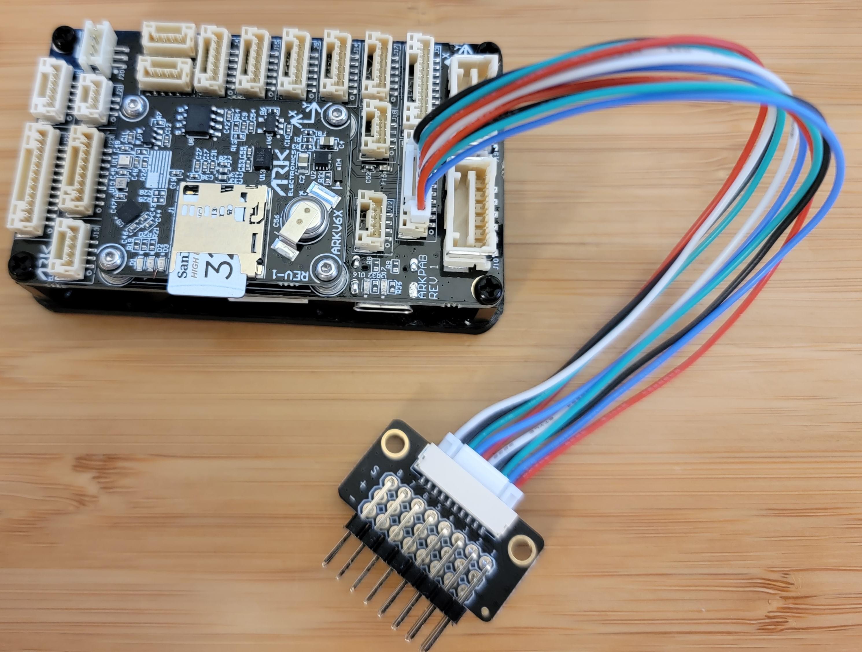
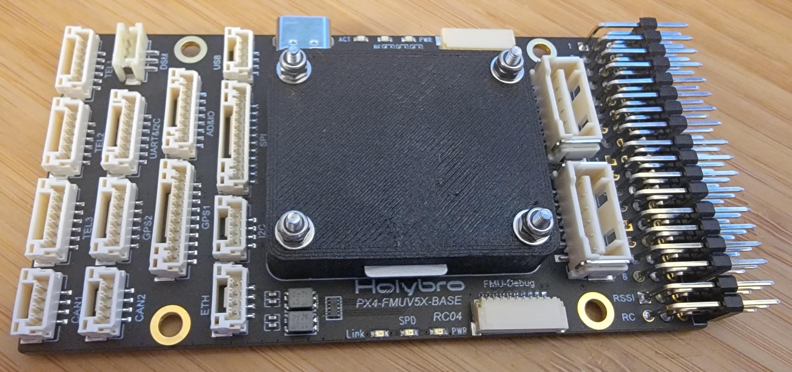
The ARK6X carrier doesn't have normal servo output connectors. Instead, it has a single JST GH connector which carries the 8 FMU servo outputs. A Holybro PWM breakout board was used to split the single JST GH PWM output connector into 8 individual servo channels.
The ARK6X carrier is shown here mounted to the base plate. Note the aft end of the carrier aligned against the two tick marks.
Finally, the ARK6X was installed on top of the mount.
Holybro 5X Carrier (Optional)
An alternative carrier board is the Holybro Pixhawk 5X carrier.
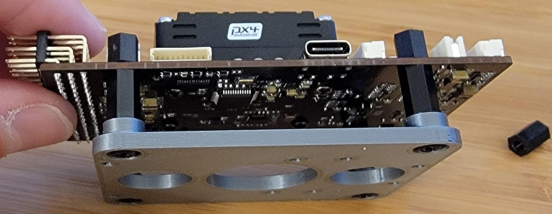
The carrier comes installed in a plastic case. While the case does look nice, it is extra weight, so the carrier was removed from the case. Once removed from the case, the ARK6X was installed, and a protective cover fitted on top.
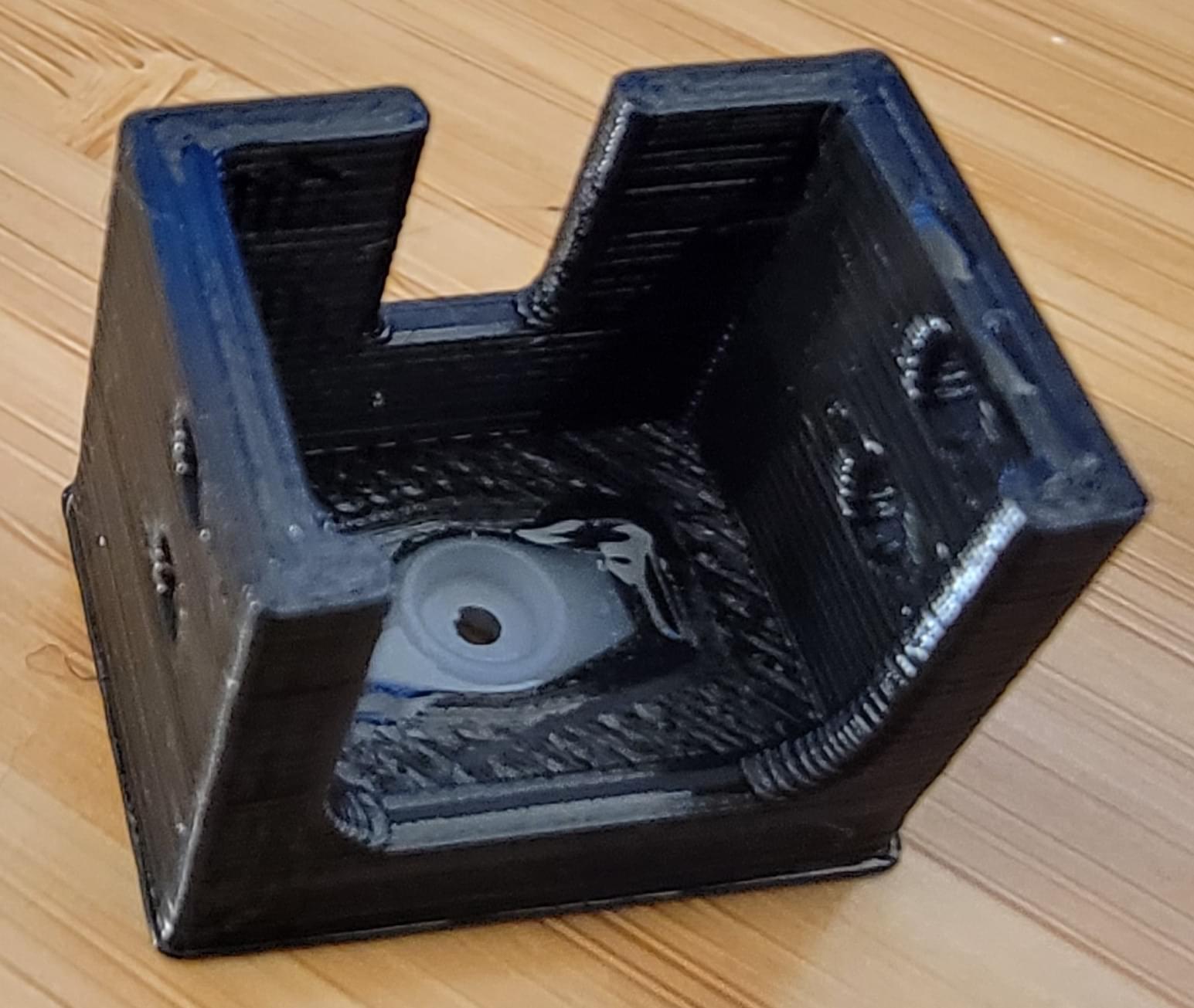
A custom mount for the Pixhawk 5X carrier board was designed and 3D printed. This mount adapts the RD2's internal mounting plate hole pattern to the mounting holes on the Pixhawk 5X carrier board.
It's important to install this mount in the correct location inside the RD2; as far aft as possible. With a large battery and the FPV pod up front, the airplane will tend to be noseheavy. Mounting the flight computer far aft will help to keep the airframe center of gravity (CG) in the correct location.
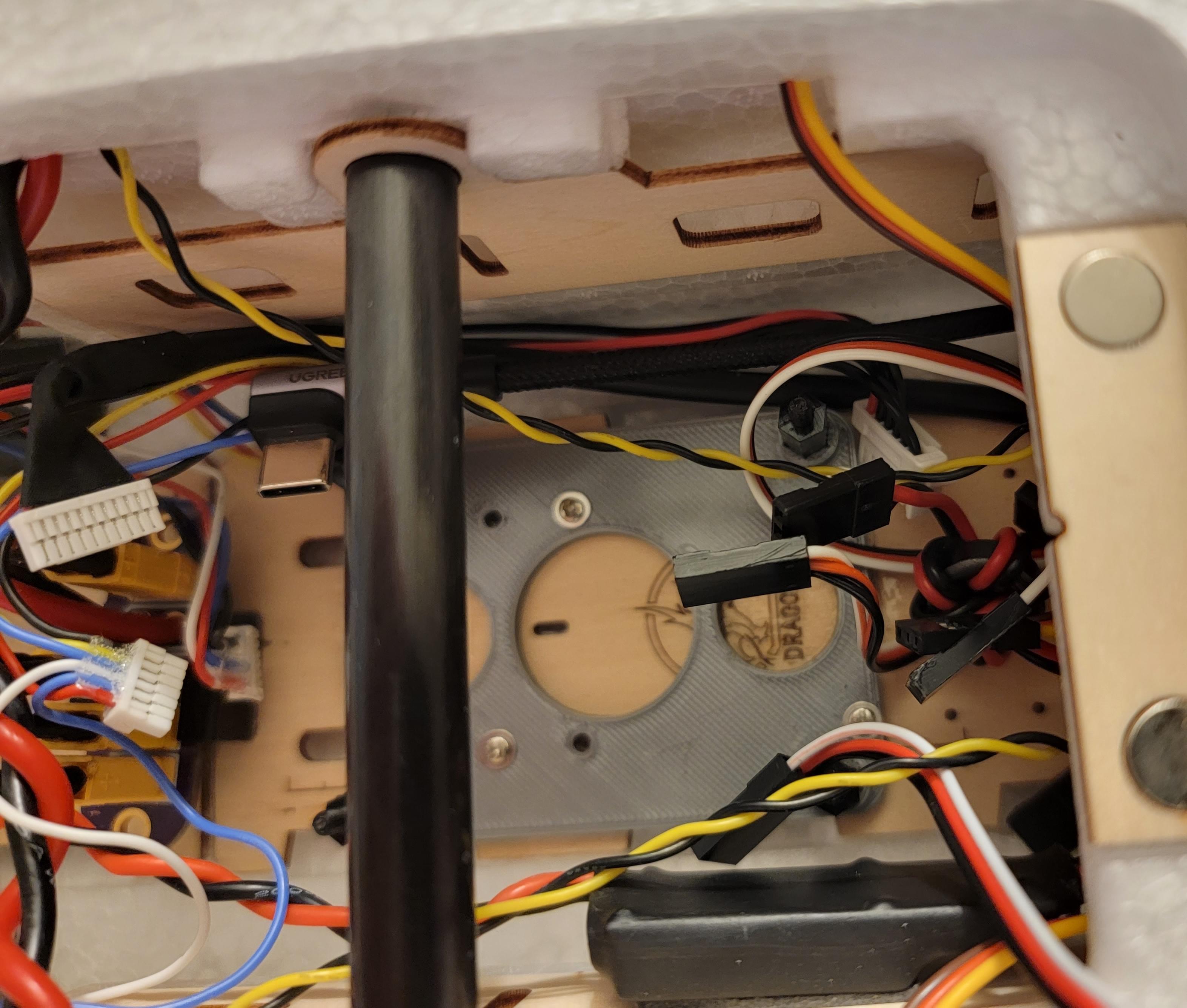
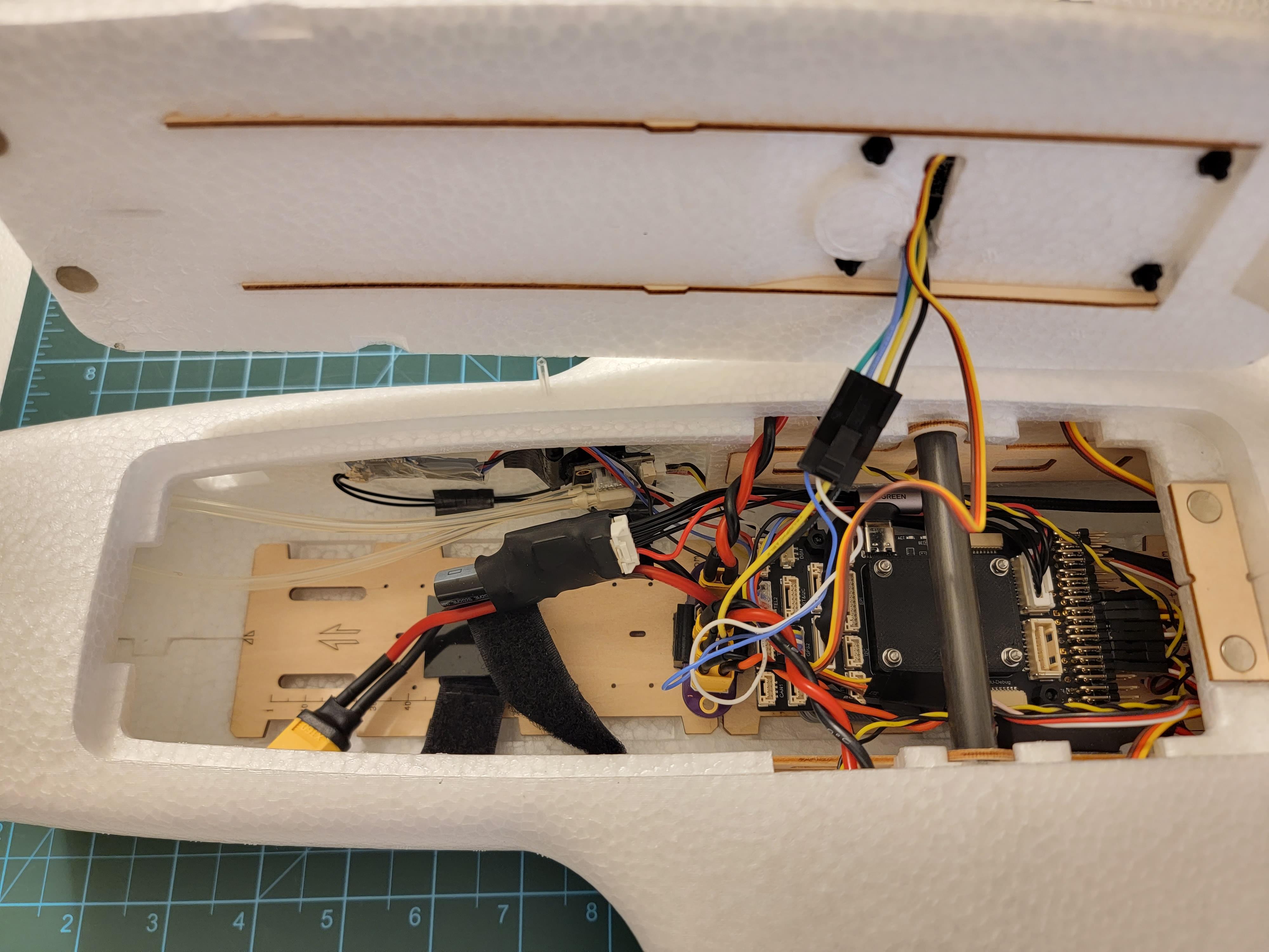
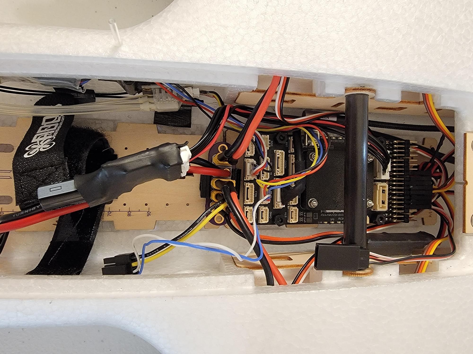
The images above show the fully completed and connected Holybro 5X carrier installation.
Electrical
Battery Power Distribution
Battery power is routed through the Holybro Power module, then to a custom designed power distribution PCB (printed circuit board). From the power distribution board, battery power is split to the BEC, both ESCs, and Caddx Vista through separate XT30 connectors.
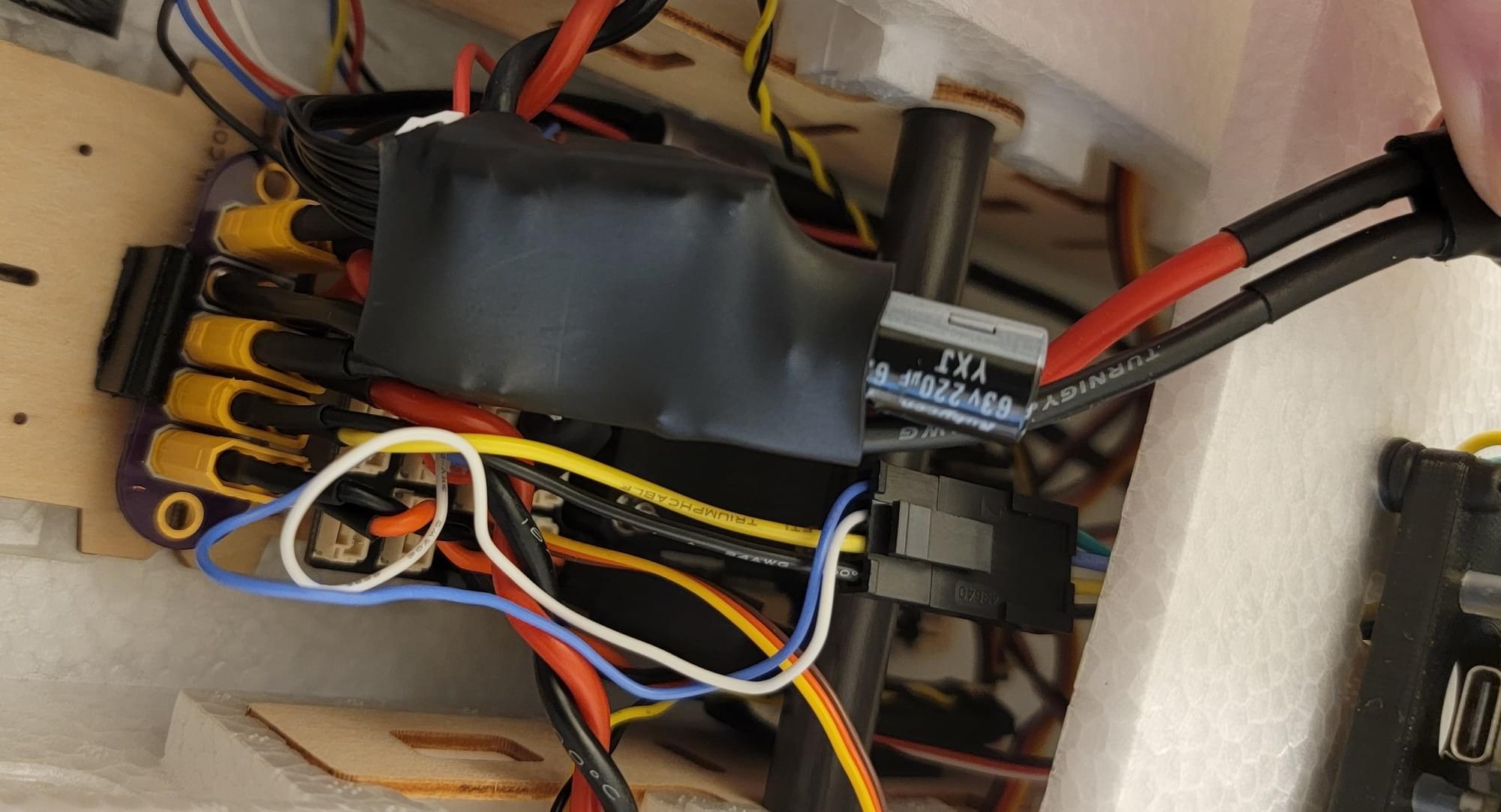
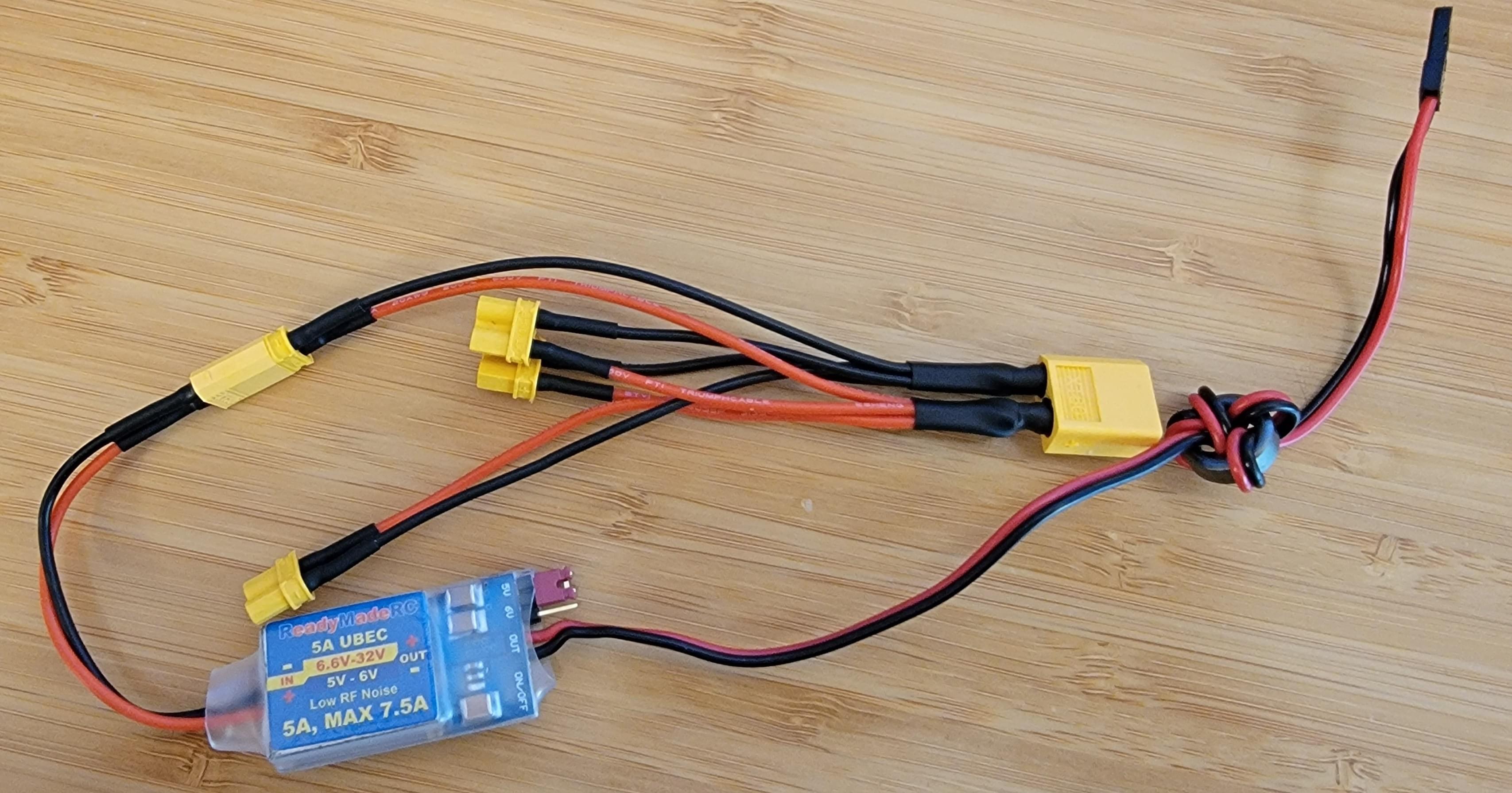
Without the custom PCB, it's still easy to distribute power to all the components in the airplane. This image shows an alternative solution constructed from an XT60 connecter wired to several XT30 connectors. The servo power BEC is also shown in this image.
Servo Power
Because the Holybro carrier does not include an onboard servo power supply, an external "BEC" is used to provide power to the servos. The input leads of the EC were soldered to a XT30 connector which was plugged into the power distribution board. The output of the BEC can be plugged into any unused servo output (I chose IO output 8).
ESCs & Motors
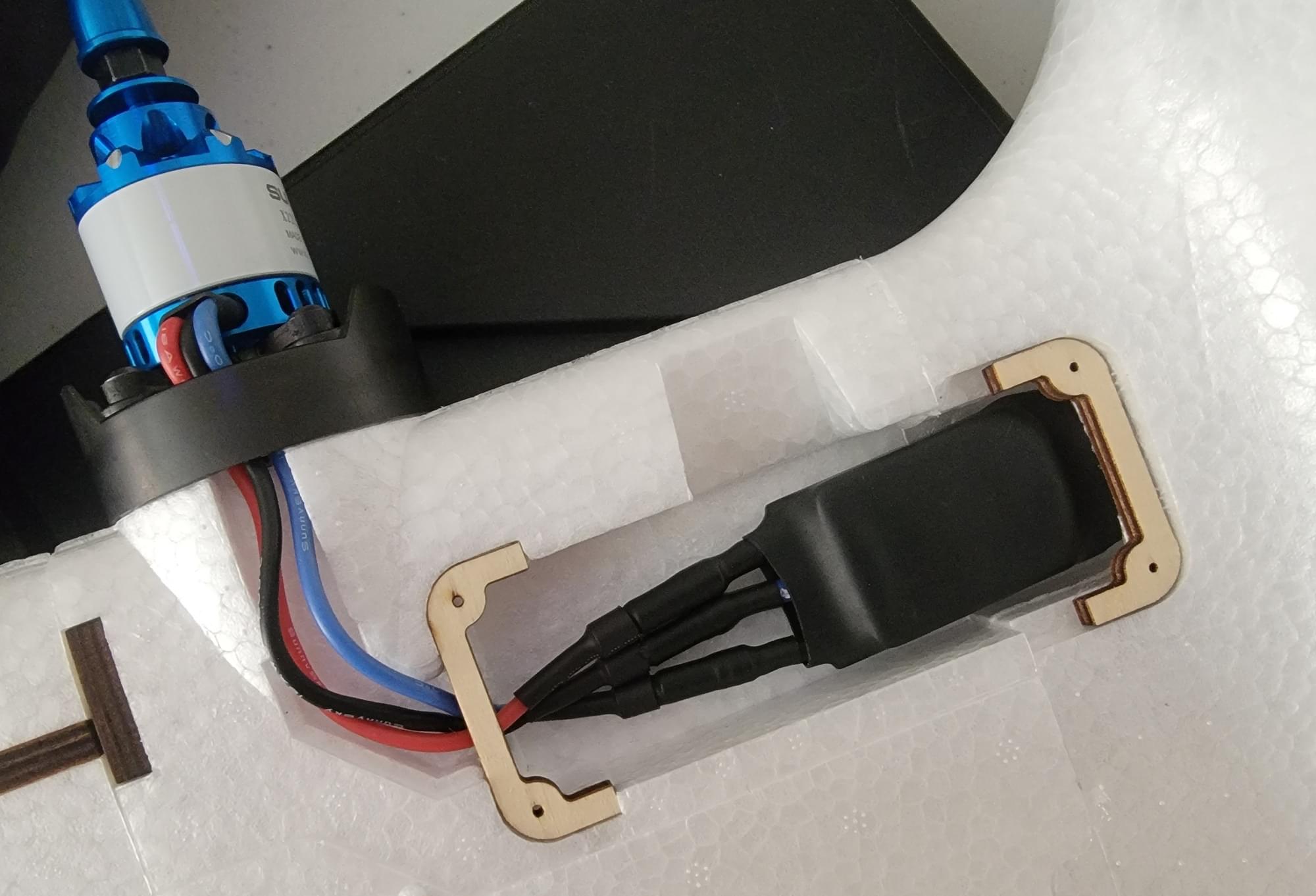
Bullet connectors were soldered to 16awg leads, which were then soldered to each phase output on each ESC. Heatshrink was shrunk over the finished ESCs and the bullet connectors from the ESCs were connected to their respective motors.
Motor direction depends on the order of the motor leads connected to the ESC. For now, take a guess on each side. If either motor is spinning the wrong way, the direction can be swapped by swapping any two connections. Correct motor direction will be checked in the final preflight checks.
Servos & ESC Signal Leads
Servos were wired to the FMU out port in the order left aileron, right aileron, left ESC, right ESC, elevator, rudder, FPV pan.
INFO
DSHOT ESC were used (not PWM as for the servos). To make efficient use of the DSHOT output port restrictions, the two ESCs must be wired to FMU output channels 3 and 4.
Airspeed Sensor & Pitot Tube
The airspeed sensor was connected to the I2C port on the FMU carrier board with the supplied JST GH I2C cable.
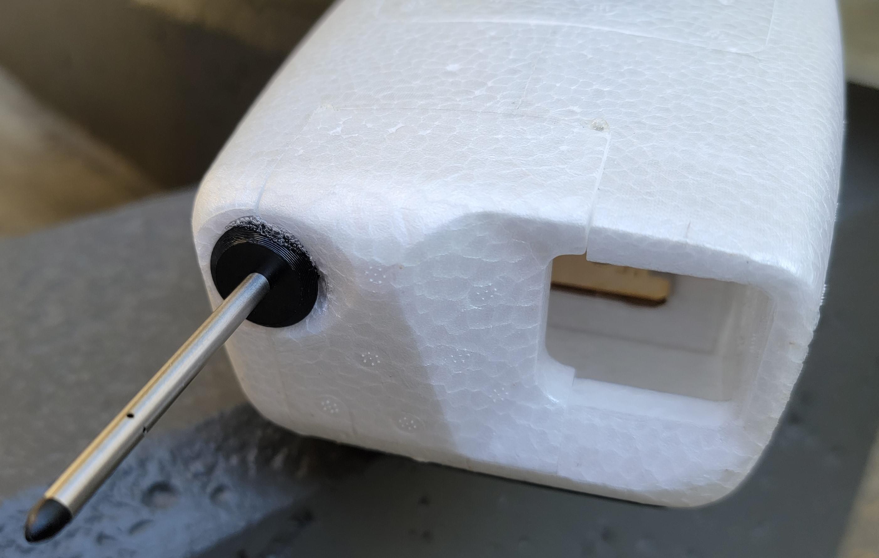
The pitot tube was pushed through the pitot tube mount and then installed in the front fpv camera cut out.
The pitot/static hoses were cut to length and installed to connect the pitot static probe to the airspeed sensor. Finally, the pitot static sensor was taped to the sidewall of the airframe (using double sided tape).
ELRS RX
A custom cable was made to connect the ELRS RX to the JST GH TELEM2 port of the FMU carrier board.
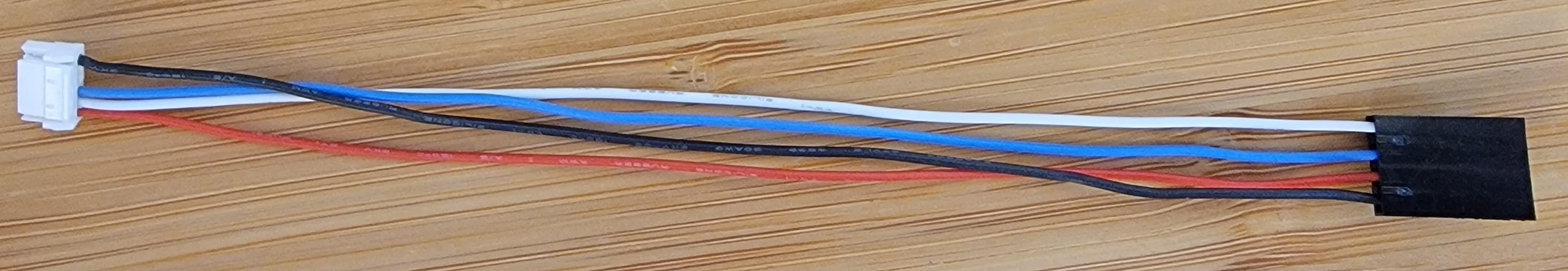
The other end of the cable was terminated to a Dupont connector to connect to the standard spaced headers on the ELRS RX. The ELRS RX was connected to the cable, and then heatshrink was used to secure the two together.
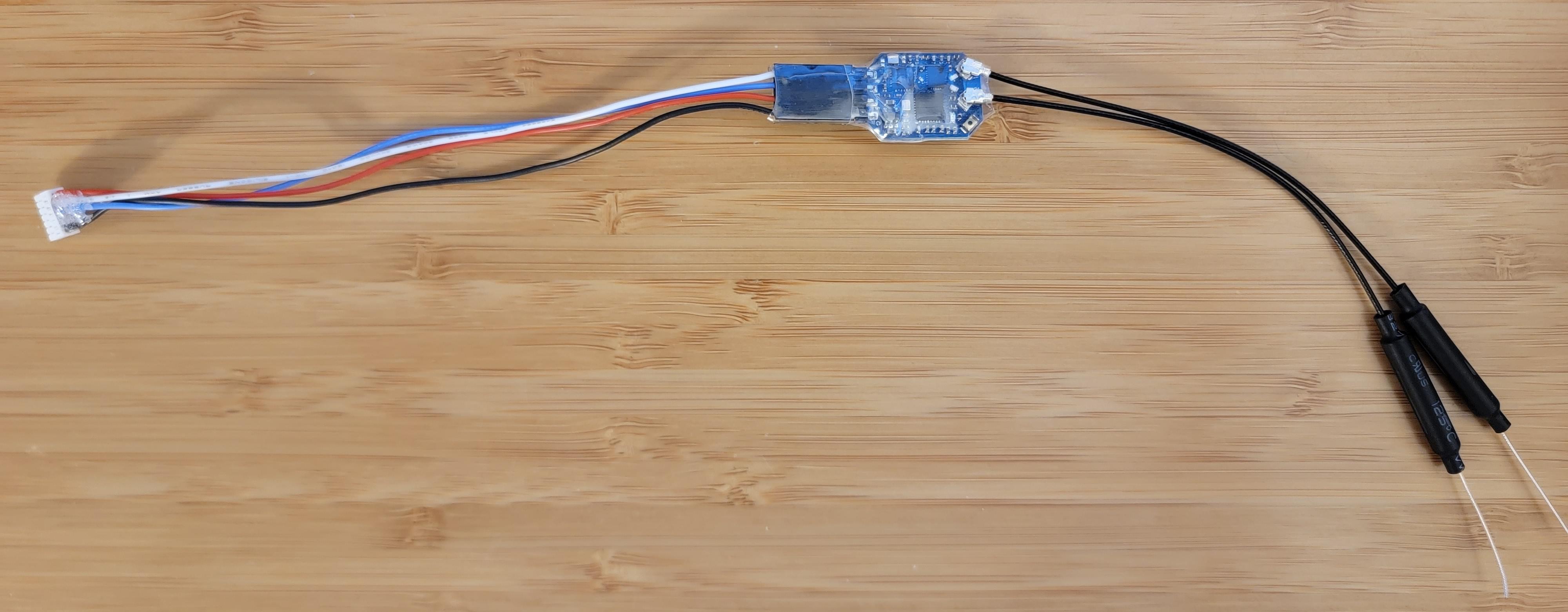
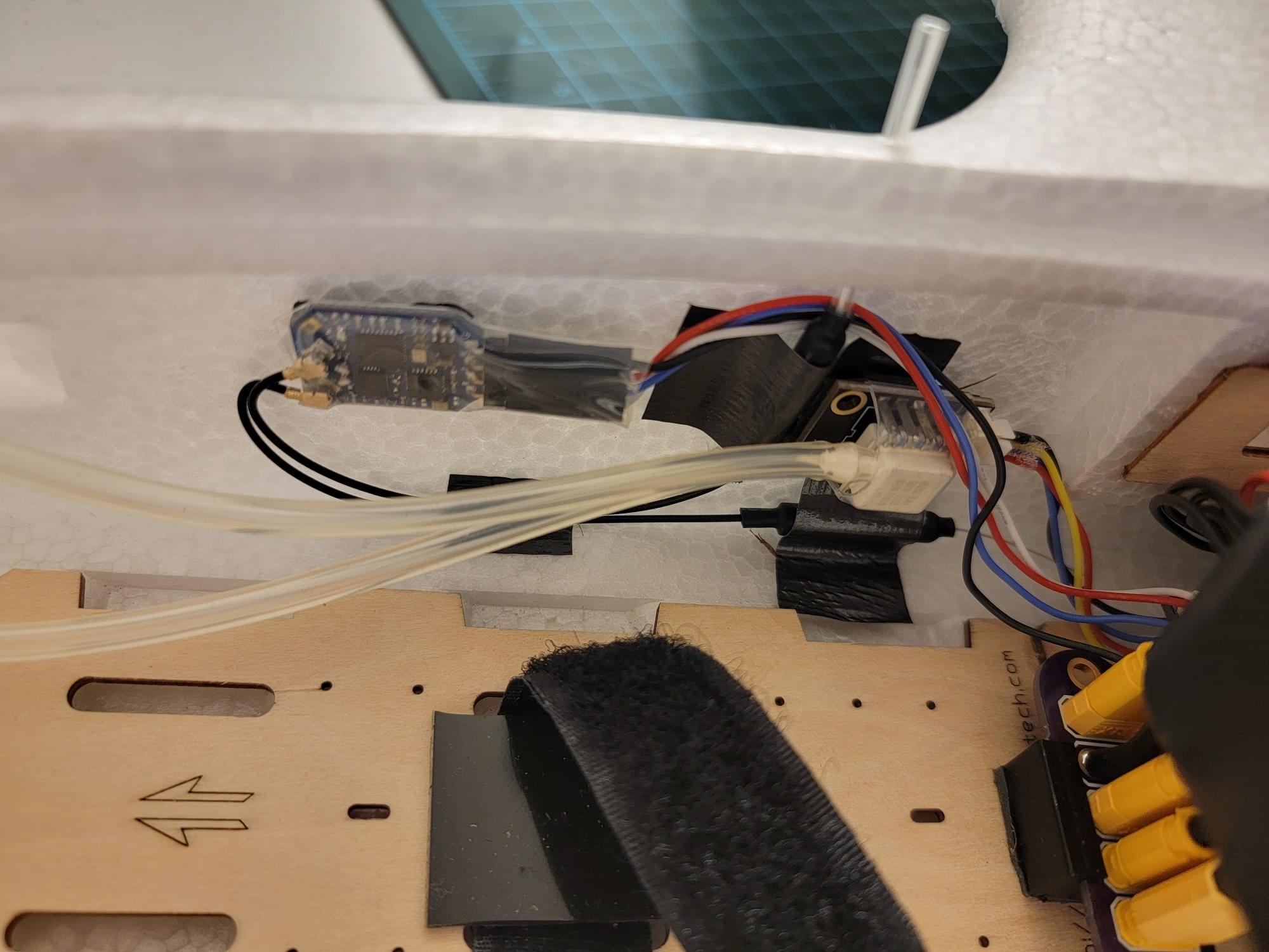
A thin radio antenna tube was pushed through the top of the airframe used to mount one of the two ELRS diversity antennas upright. The second diversity antenna was taped to the sidewall of the airframe, 90 degrees from the alignment of the first antenna. The ELRS RX was attached to the sidewall of the airframe next to the airspeed pressure sensor, using double-sided tape.
USB
A right angle USB C extension cable was used to allow easy access to the USB C port on the FMU.
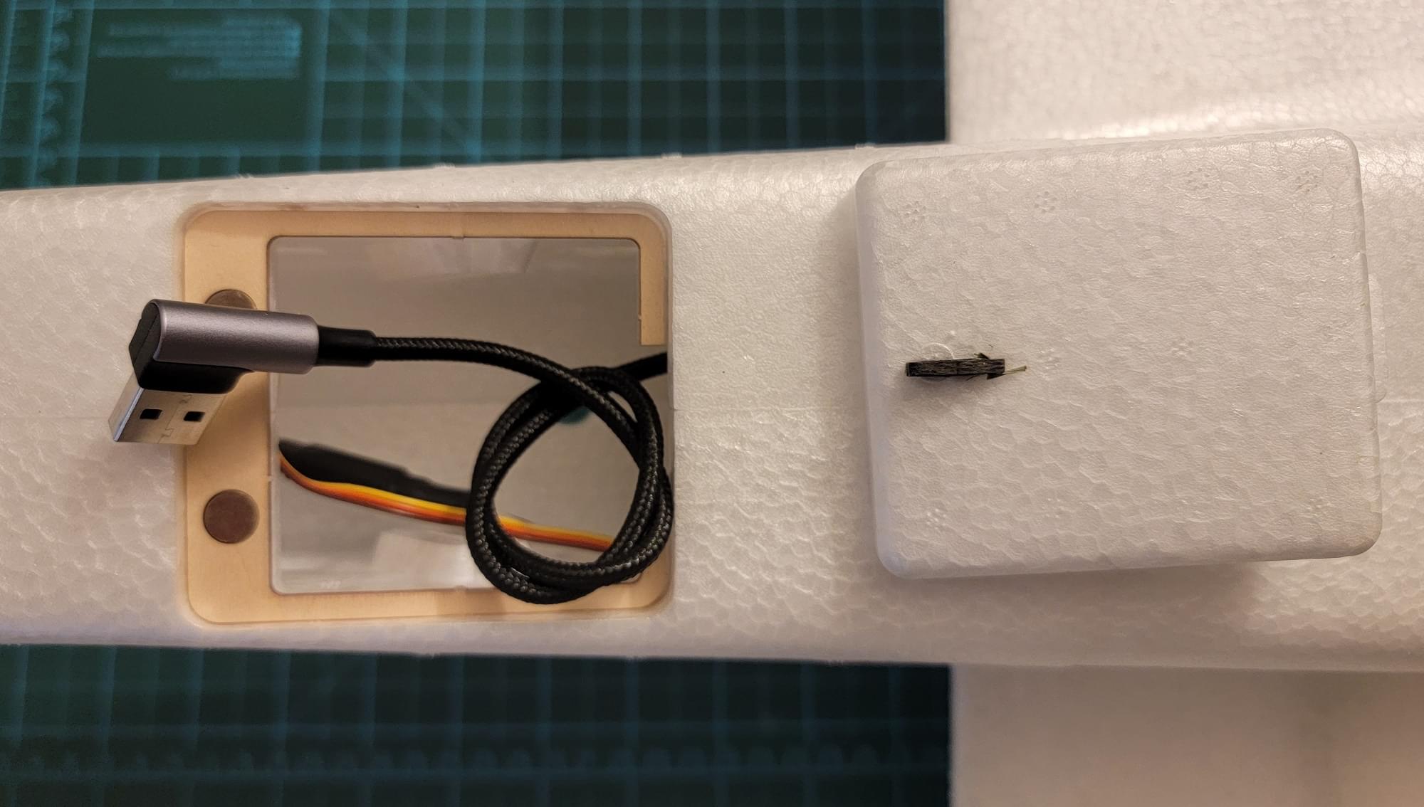
The cable was installed such that it escapes the pixhawk heading towards the aft of the airplane. The cable continues to run to the rear hatch, where the excess length can be securely wound into a knot. Access to this cable can be accomplished by simply removing the rear hatch and unknotting the cable.
Firmware Build
You can't use prebuilt PX4 release (or main) firmware for this vehicle, as it depends on PX4 modules crsf_rc and msp_osd that are not included by default.
These require some custom configuration to enable.
First, follow this guide to setup a development environment and this guide to get the PX4 source code.
Once a build environment has been setup, open a terminal and cd into the PX4-Autopilot directory. To launch the PX4 board config tool (menuconfig) run:
make ark_fmu-v6x_default boardconfigcrsf_rc Module
PX4 includes a standalone CRSF parser module which supports telemetry and CRSF LinkStatistics. To use this module, the default rc_input module must be disabled and the crsf_rc module must be enabled.
- In the PX4 board config tool, navigate to the
driverssubmenu, then scroll down to highlightrc_input. - Use the enter key to remove the
*fromrc_inputcheckbox. - Scroll to highlight the
RCsubmenu, then press enter to open it. - Scroll to highlight
crsf_rcand press enter to enable it. - Save and exit the PX4 board config tool.
For more information see TBS Crossfire (CRSF) Telemetry.
msp_osd Module
The msp_osd module streams MSP telemetry to a selected serial port. The Caddx Vista Air Unit supports listening to MSP telemetry and will show the received telemetry values in its OSD (on screen display).
- In the PX4 board config tool, navigate to the
driverssubmenu, then scroll down to highlightOSD. - Use the enter key to open the
OSDsubmenu - Scroll down to highlight
msp_osdand press enter to enable it
Building & Flashing
Once the msp_osd and crsf_rc modules are enabled and the rc_input module is disabled, the firmware source must be compiled and the resulting image flashed to the FMU.
To compile and flash the firmware, connect the FMU/Carrier to the build host PC via USB and run:
make ark_fmu-v6x_default uploadPX4 Configuration
Parameter Config
This param file contains the custom PX4 parameter configuration for this build, including radio setup, tuning and sensor config. Load the file via QGC using the instructions at Parameters> Tools (QGC User Guide).
You may need to modify some parameters for your build In particular you should check:
- MSP_OSD_CONFIG param must match serial port which is connected to the Caddx Vista (in this build,
/dev/ttyS7). - RC_CRSF_PRT_CFG param must match the serial port which is connected to the ELRS RX (in this build,
Telem 1).
Radio Setup
You should enable Manual, Acro, and Position modes on your controller (at least for the first flight). For instructions see Flight mode Configuration
We also recommend configuring an autotuning switch for the first flight, as this makes it easier to enable/disable autotuning while flying.
The channel mappings for this build are included in the supplied params file. The channel order is throttle, roll, pitch, yaw, (blank), and flight mode
INFO
ExpressLRS requires AUX1 as an "arming channel". This arming channel is separate from PX4's arming mechanism and is used to tell the ELRS TX that is can switch into high transmit power.
In the PX4 channel mappings, I simply skip over this channel. On my transmitter, this channel is set to always be "high", so ELRS is always armed.
Motor Setup & Prop Installation
Motors and flight control surface setup done in the Actuator section. The supplied params file maps the actuators as described in this build.
The RD2 kit comes with clockwise and counter clockwise propellers for counter rotating motors. With counter rotating props, the airplane can be set up such that it has no critical motors.
With no critical motors, controllability will be maximized if a motor fails. The motor direction should be set such that props should turn towards the fuselage on top of the plane. In other words, if you look at the left motor with the airplane facing away from you, it should spin clockwise while the right motor should spin counter clockwise.
With the propellers removed, power the airplane up and use the Actuator test in QGC to spin up the motors. If the left or right motor does not spin in the correct direction, swap two of its ESC leads and check it again. Finally, when both motors are spinning the correct directions, use a wrench to attach the propellers.
Final Checks
Prior to the first flight, a comprehensive preflight must be conducted.
I recommend checking the following items:
- Sensor calibration (QGC)
- Mag calibration
- Accelerometer calibration
- Airspeed calibration
- Level horizon calibration
- Check control surface deflection
- Right stick -> Right aileron goes up, left aileron goes down
- Left stick -> Left aileron goes up, right aileron goes down
- Stick back -> elevator goes up -Stick forward -> elevator goes down
- Left rudder -> Rudder goes left
- Right rudder -> Rudder goes right
- Check Px4 inputs (in
stabilized mode) - Roll right -> Right Aileron goes down
- Roll left -> Left aileron goes down
- Pitch up -> Elevator goes down
- Pitch down -> Elevator goes up
First Flight
I recommend performing the first takeoff in manual mode. Because this airplane has no landing gear, you will either need to throw the airplane yourself, or ideally have a helper throw it. When throwing any airplane, throw at a slightly nose up attitude with full throttle.
It's critical to be ready to give aft stick input to prevent the airplane from impacting the ground if it happens to be trimmed nosedown. Once the airplane is successfully airborne, cruise up to an altitude of a few hundred feet and switch to Acro mode. This is a good time to use Autotuning to tune the airframe.
If the airplane is well behaved in Acro mode, switch to Position mode.
Build Results & Performance
Overall, this build was a success. The RD2 flies well in this configuration and has plenty of room onboard for sensors and additional hardware.
Performance
- Stall speed: 15mph indicated
- Cruise speed: 35-50mph
- Endurance: ~40 minutes at 28mph
Videos & Flight Logs
FPV video of flight log: