Holybro Pix32 v5
WARNING
PX4 does not manufacture this (or any) autopilot. Contact the manufacturer for hardware support or compliance issues.
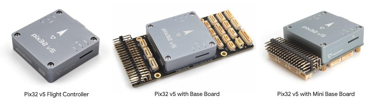
Pix32 v5® is an advanced autopilot flight controller designed and made by Holybro®. It is optimized to run on PX4 firmware, which is intended for both academic and commercial developers. It is based on the Pixhawk-project FMUv5 open hardware design and runs PX4 on the NuttX OS. It can be regarded as a variant version of Pixhawk4.
The Pix32 v5 is designed for pilots who need a high power, flexible and customisable flight control system. It is comprised of a separate flight controller and carrier (base) board, which are connected by a 100pin connector. This design allows users to either select a base board made by Holybro, or customize their own.
INFO
This flight controller is manufacturer supported.
Quick Summary
- Main FMU Processor: STM32F765
- 32 Bit Arm® Cortex®-M7, 216MHz, 2MB memory, 512KB RAM
- IO Processor: STM32F100
- 32 Bit Arm® Cortex®-M3, 24MHz, 8KB SRAM
- On-board sensors:
- Accel/Gyro: ICM-20689
- Accel/Gyro: BMI055 or ICM20602
- Magnetometer: IST8310
- Barometer: MS5611
- GPS: u-blox Neo-M8N GPS/GLONASS receiver; integrated magnetometer IST8310
- Interfaces:
- 8-16 PWM outputs (8 from IO, 8 from FMU)
- 3 dedicated PWM/Capture inputs on FMU
- Dedicated R/C input for CPPM
- Dedicated R/C input for Spektrum / DSM and S.Bus with analog / PWM RSSI input
- Dedicated S.Bus servo output
- 5 general purpose serial ports
- 2 with full flow control
- 1 with separate 1.5A current limit
- 3 I2C ports
- 4 SPI buses
- 1 internal high speed SPI sensor bus with 4 chip selects and 6 DRDYs
- 1 internal low noise SPI bus dedicated for
- Barometer with 2 chip selects, no DRDYs
- 1 internal SPI bus dedicated for FRAM
- Supports dedicated SPI calibration EEPROM located on sensor module
- 1 external SPI buses
- Up to 2 CANBuses for dual CAN with serial ESC
- Each CANBus has individual silent controls or ESC RX-MUX control
- Analog inputs for voltage / current of 2 batteries
- 2 additional analog inputs
- Electrical System:
- Power module output: 4.9~5.5V
- Max input voltage: 6V
- Max current sensing: 120A
- USB Power Input: 4.75~5.25V
- Servo Rail Input: 0~36V
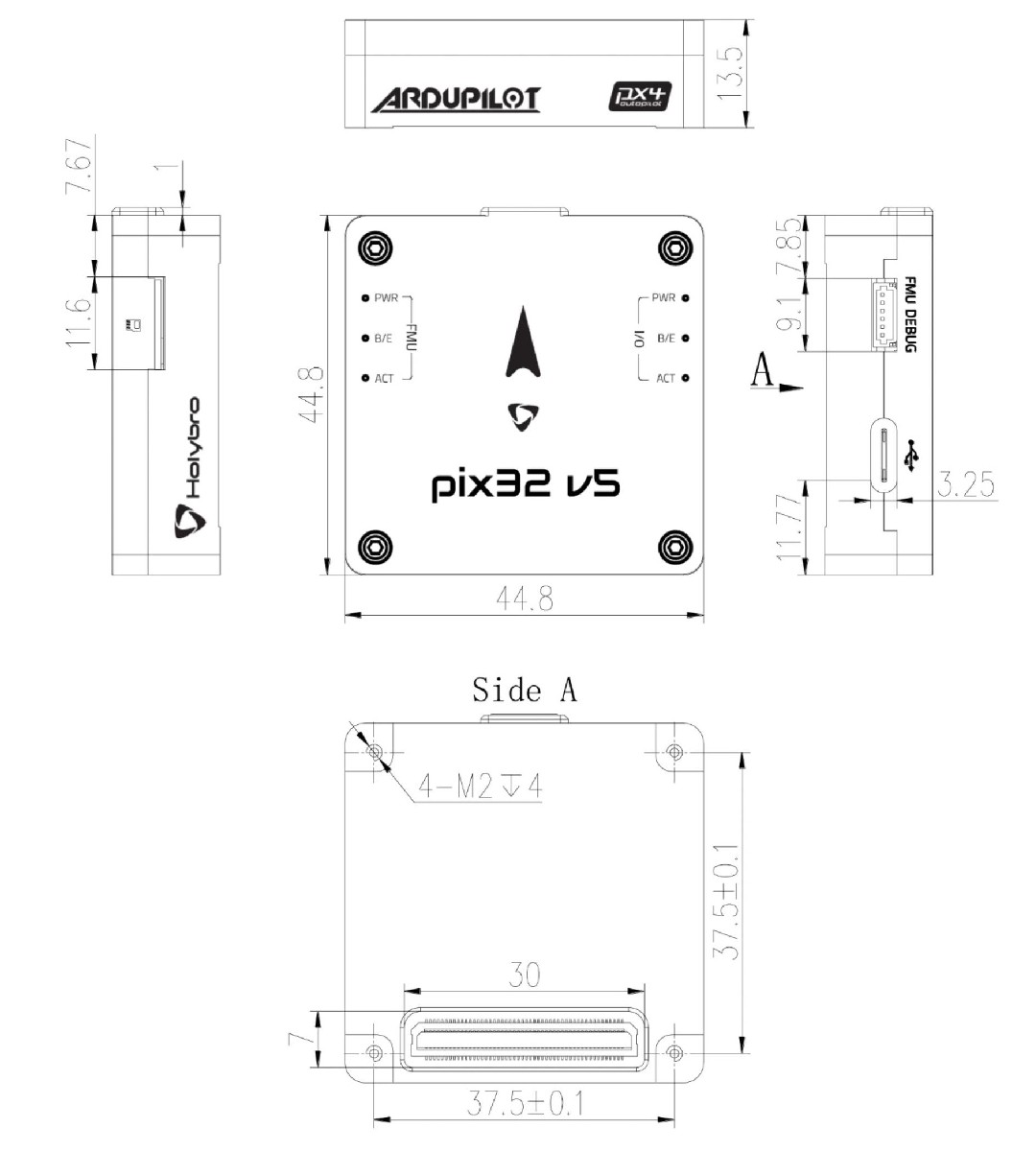
- Weight and Dimensions:
- Dimensions: 45x45x13.5mm
- Weight: 33.0g
- Environmental Data, Quality & Reliability:
- Operating temperature: -40 ~ 85°c
- Storage temp. -40~85℃
- CE
- FCC
- RoHS compliant (lead-free)
Additional information can be found in the Pix32 V5 Technical Data Sheet.
Where to Buy
Order from Holybro website.
Assembly/Setup
The Pix32 v5 Wiring Quick Start provides instructions on how to assemble required/important peripherals including GPS, Power Management Board etc.
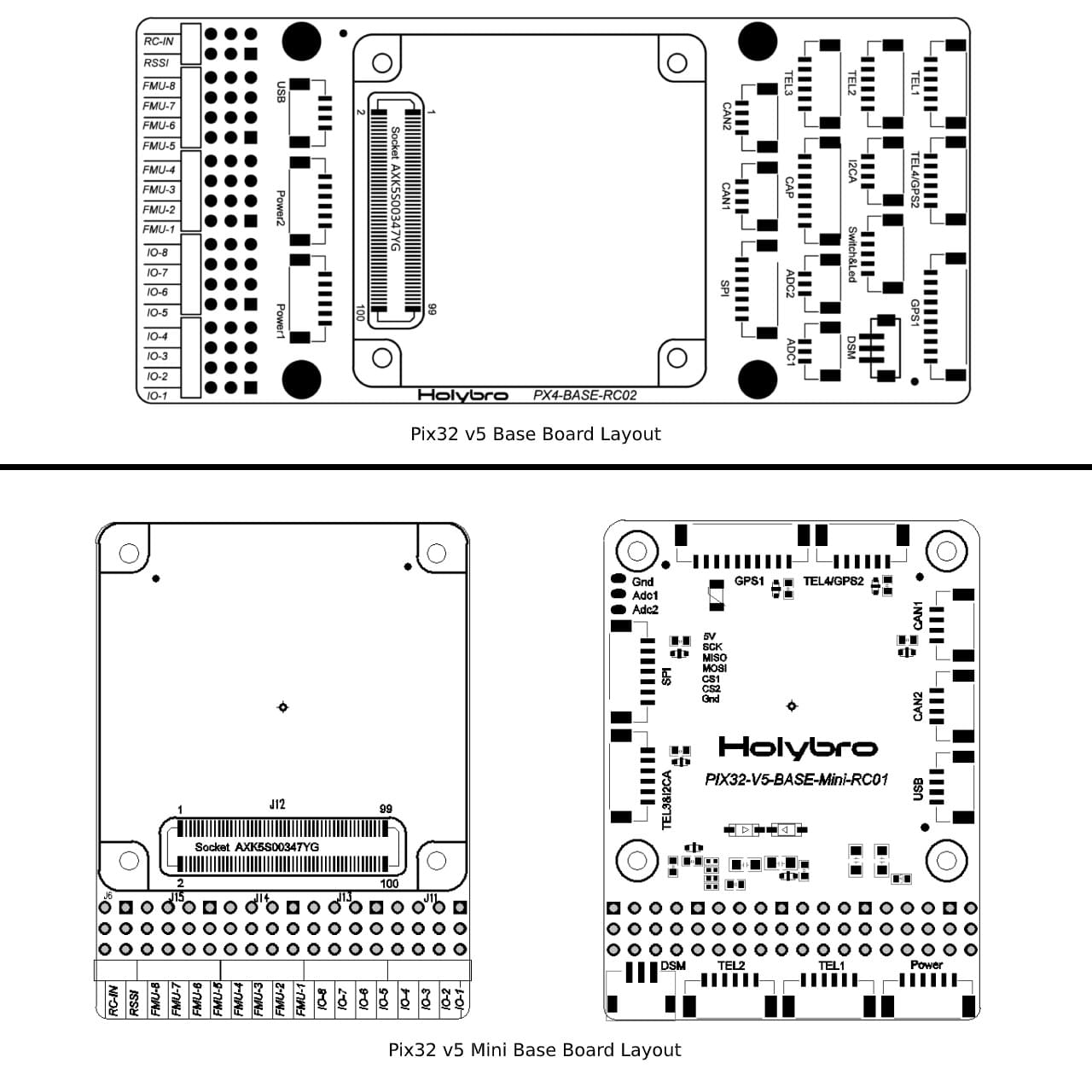
Base Board Layouts
Pinouts
Dimensions
Voltage Ratings
Pix32 v5 can be triple-redundant on the power supply if three power sources are supplied. The three power rails are: POWER1, POWER2 and USB.
INFO
The output power rails FMU PWM OUT and I/O PWM OUT (0V to 36V) do not power the flight controller board (and are not powered by it). You must supply power to one of POWER1, POWER2 or USB or the board will be unpowered.
Normal Operation Maximum Ratings
Under these conditions all power sources will be used in this order to power the system:
- POWER1 and POWER2 inputs (4.9V to 5.5V)
- USB input (4.75V to 5.25V)
Absolute Maximum Ratings
Under these conditions the system will not draw any power (will not be operational), but will remain intact.
- POWER1 and POWER2 inputs (operational range 4.1V to 5.7V, 0V to 10V undamaged)
- USB input (operational range 4.1V to 5.7V, 0V to 6V undamaged)
- Servo input: VDD_SERVO pin of FMU PWM OUT and I/O PWM OUT (0V to 42V undamaged)
Building Firmware
TIP
Most users will not need to build this firmware! It is pre-built and automatically installed by QGroundControl when appropriate hardware is connected.
To build PX4 for this target:
make holybro_pix32v5_defaultDebug Port
The system's serial console and SWD interface runs on the FMU Debug port
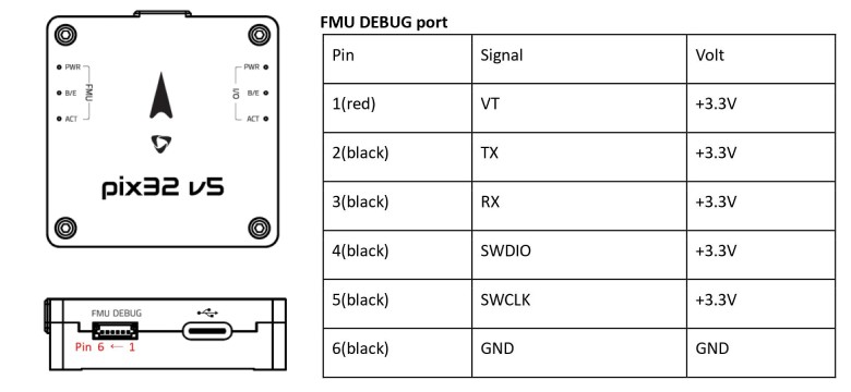
The pinout uses the standard Pixhawk Debug Mini interface defined in the Pixhawk Connector Standard.
Peripherals
Supported Platforms / Airframes
Any multicopter / airplane / rover or boat that can be controlled with normal RC servos or Futaba S-Bus servos. The complete set of supported configurations can be seen in the Airframes Reference.