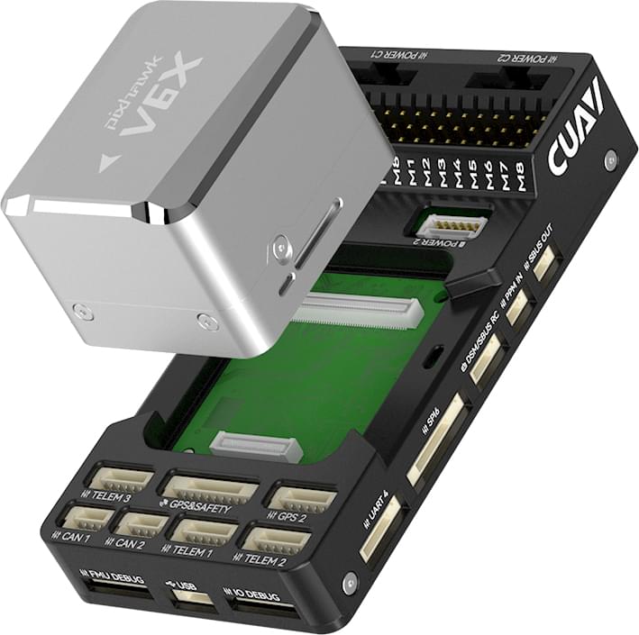
CUAV Pixhawk V6X
WARNING
PX4 does not manufacture this (or any) autopilot. Contact the manufacturer for hardware support or compliance issues.
Pixhawk V6X® is the latest update to the successful family of Pixhawk® flight controllers designed and made in collaboration with CUAV® and the PX4 team.
It is based on the Pixhawk® Autopilot FMUv6X Standard, Autopilot Bus Standard, and Connector Standard.
TIP
This autopilot is supported by the PX4 maintenance and test teams.
Pixhawk® V6X brings you the ultimate in performance, stability and reliability in all aspects.
- Arm® Cortex®-M7 processor (STM32H753) with Floating Point Unit (FPU), 480MHz high-speed operations and 2MB flash. Developers can be more productive and efficient, allowing for more complex algorithms and models.
- High-performance on-board, low-noise IMU and automotive-grade magnetic compass based on FMUv6X open standard. It aims to achieve better stability and anti-interference ability.
- Triple redundant IMU & double redundant barometer on separate buses. When the PX4 Autopilot detects a sensor failure, the system seamlessly switches to another to maintain flight control reliability.
- An independent LDO powers every sensor set with independent power control. A vibration isolation System to filter out high-frequency vibration and reduce noise to ensure accurate readings, allowing vehicles to reach better overall flight performances.
- External sensor bus (SPI5) has two chip select lines and data-ready signals for additional sensors and payload with SPI-interface.
- Integrated Microchip Ethernet PHY for high-speed communication over Ethernet with onboard devices such as mission computers.
- Newly designed vibration isolation system to filter out high frequency vibration and reduce noise to ensure accurate readings.
- IMUs are temperature-controlled by onboard heating resistors, allowing optimum working temperature of IMUs
- Modular flight controller: separated IMU, FMU, and Base system connected by a 100-pin & a 50-pin Pixhawk® Autopilot Bus connector.
The Pixhawk® V6X is ideal for corporate research labs, academic research and commercial applications.
Processors & Sensors
- FMU Processor: STM32H753
- 32 Bit Arm® Cortex®-M7, 480MHz, 2MB flash memory, 1MB RAM
- IO Processor: STM32F103
- 32 Bit Arm® Cortex®-M3, 72MHz, 20KB SRAM
- On-board sensors
- Accel/Gyro: BMI088
- Accel/Gyro: ICM-42688-P
- Accel/Gyro: ICM-20649
- Mag: RM3100
- Barometer: 2x ICP-20100
Electrical data
- Voltage Ratings:
- Max input voltage: 5.7V
- USB Power Input: 4.75~5.25V
- Servo Rail Input: 0~9.9V
- Current Ratings:
- TELEM1 and GPS2 combined output current limiter: 1.5A
- All other port combined output current limiter: 1.5A
Interfaces
- 16- PWM servo outputs
- 1 Dedicated R/C input for Spektrum / DSM and S.Bus with analog / PWM RSSI input
- 3 TELEM Ports(with full flow control)
- 1 UART4(Serial and I2C)
- 2 GPS ports
- 1 full GPS plus Safety Switch Port(GPS1)
- 1 basic GPS port(with I2C,GPS2)
- 2 USB Ports
- 1 TYPE-C
- JST GH1.25
- 1 Ethernet port
- Transformerless Applications
- 100Mbps
- 1 SPI bus
- 2 chip select lines
- 2 data-ready lines
- 1 SPI SYNC line
- 1 SPI reset line
- 2 CAN Buses for CAN peripheral
- CAN Bus has individual silent controls or ESC RX-MUX control
- 4 power input ports
- 2 Dronecan/UAVCAN power inputs
- 2 SMBUS/I2C power inputs
- 1 AD & IO port
- 2 additional analog input(3.3 and 6.6v)
- 1 PWM/Capture input
- 2 Dedicated debug
- FMU debug
- IO debug
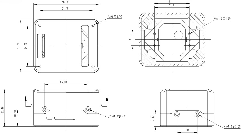
Mechanical data
- Weight
- Flight Controller Module: 99g
- Core module: 43g
- Baseboard: 56g
- Operating & storage temperature: -20 ~ 85°c
- Size
Flight controller
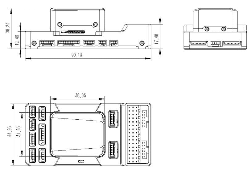
Core module
Where to Buy
Order from CUAV.
Assembly/Setup
The Pixhawk V6X Wiring Quick Start provides instructions on how to assemble required/important peripherals including GPS, Power Module etc.
Pinouts
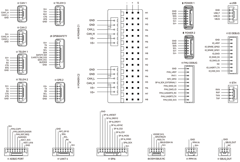
Notes:
- The camera capture pin (
PI0) is pin 2 on the AD&IO port, marked above asFMU_CAP1.
Serial Port Mapping
| UART | Device | Port |
|---|---|---|
| USART1 | /dev/ttyS0 | GPS |
| USART2 | /dev/ttyS1 | TELEM3 |
| USART3 | /dev/ttyS2 | Debug Console |
| UART4 | /dev/ttyS3 | UART4 |
| UART5 | /dev/ttyS4 | TELEM2 |
| USART6 | /dev/ttyS5 | PX4IO/RC |
| UART7 | /dev/ttyS6 | TELEM1 |
| UART8 | /dev/ttyS7 | GPS2 |
Voltage Ratings
Pixhawk V6X can be triple-redundant on the power supply if three power sources are supplied. The three power rails are: POWERC1/POWER1, POWERC2/POWER2 and USB.
- POWER C1 and POWER C2 are DroneCAN/UAVCAN battery interfaces (recommended);POWER1 and POWER2 are SMbus/I2C battery interfaces (backup).
- POWER C1 and POWER1 use the same power switch, POWER C2 and POWER2 use the same power switch.
Normal Operation Maximum Ratings
Under these conditions all power sources will be used in this order to power the system:
- POWER C1, POWER C2, POWER1 and POWER2 inputs (4.75V to 5.7V)
- USB input (4.75V to 5.25V)
Absolute Maximum Ratings
Under these conditions the system will not draw any power (will not be operational), but will remain intact.
- POWER1 and POWER2 inputs (operational range 4.7V to 5.7V, 0V to 10V undamaged)
- USB input (operational range 4.7V to 5.7V, 0V to 6V undamaged)
- Servo input:
VDD_SERVOpin of FMU PWM OUT and I/O PWM OUT (0V to 42V undamaged)
Voltage monitoring
Digital DroneCAN/UAVCAN battery monitoring is enabled by default (see Quickstart > Power).
INFO
Analog battery monitoring via an ADC is not supported on this particular board, but may be supported in variations of this flight controller with a different baseboard.
Building Firmware
TIP
Most users will not need to build this firmware! It is pre-built and automatically installed by QGroundControl when appropriate hardware is connected.
To build PX4 for this target:
make px4_fmu-v6x_defaultDebug Port
The PX4 System Console and SWD interface run on the FMU Debug port.
The pinouts and connector comply with the Pixhawk Debug Full interface defined in the Pixhawk Connector Standard interface (JST SM10B connector).
| Pin | Signal | Volt |
|---|---|---|
| 1 (red) | Vtref | +3.3V |
| 2 (blk) | Console TX (OUT) | +3.3V |
| 3 (blk) | Console RX (IN) | +3.3V |
| 4 (blk) | SWDIO | +3.3V |
| 5 (blk) | SWCLK | +3.3V |
| 6 (blk) | SWO | +3.3V |
| 7 (blk) | NFC GPIO | +3.3V |
| 8 (blk) | PH11 | +3.3V |
| 9 (blk) | nRST | +3.3V |
| 10 (blk) | GND | GND |
For information about wiring and using this port see:
- PX4 System Console (Note, the FMU console maps to USART3).
- SWD Debug Port
Peripherals
Supported Platforms / Airframes
Any multicopter / airplane / rover or boat that can be controlled with normal RC servos or Futaba S-Bus servos. The complete set of supported configurations can be seen in the Airframes Reference.