RadiolinkPIX6 Flight Controller
PX4 v1.17WARNING
PX4 does not manufacture this (or any) autopilot. Contact the manufacturer for hardware support or compliance issues.
The autopilot is recommended for commercial systems integration, but is also suitable for academic research and any other use.

The Radiolink PIX6 is a high-performance flight controller. Featuring STM32F7 CPU, vibration isolation of IMUs, redundant IMUs, integrated OSD chip, IMU heating, and DShot.
INFO
This flight controller is manufacturer supported.
Quick Summary
- Processor
- 32-bit ARM Cortex M7 core with DPFPU - STM32F765VIT6
- 216 MHz/512 KB RAM/2 MB Flash
- 32-bit IOMCU co-processor - STM32F100
- 32KB FRAM - FM25V02A
- AT7456E OSD
- Sensors
- Bosch BMI088 IMU (accel, gyro)
- InvenSense ICM-42688 IMU (accel, gyro)
- SPA06 barometer
- IST8310 magnetometer
- Power
- SMBUS/I2C Power Module Inputs (I2C)
- voltage and current monitor inputs (Analog)
- Interfaces
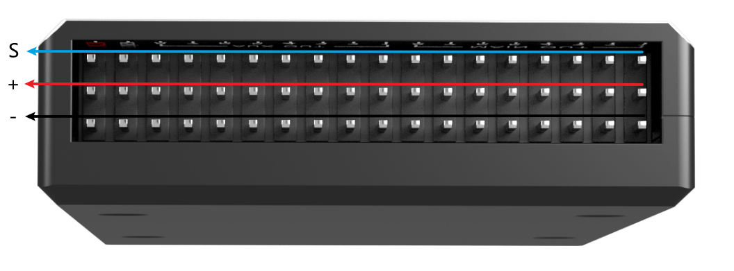
- 16 PWM Outputs with independent power rail for external power source
- 5x UART serial ports, 2 with HW flow control
- Camera Input and Video Output
- PPM/SBUS input, DSM/SBUS input
- RSSI (PWM or voltage) input
- I2C, SPI, 2x CAN, USB
- 3.3V and 6.6V ADC inputs
- Buzzer and Safety Switch
- microSD card
- Weight and Dimensions:
- Weight 80g
- Size 94mm x 51.5mm x 14.5mm
Where to Buy
Radiolink Amazon(International users)
Radiolink Taobao(China Mainland user)
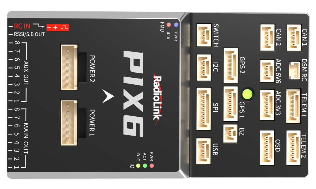
Connector assignments
Top View
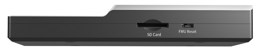
Left View
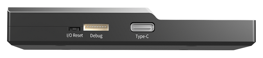
Right View
Rear View
Pinouts
Unless noted otherwise all connectors are JST GH.
TELEM1, TELEM2 ports
| Pin | Signal | Volt |
|---|---|---|
| 1 | VCC | +5V |
| 2 | TX(OUT) | +3.3V |
| 3 | RX(IN) | +3.3V |
| 4 | CTS | +3.3V |
| 5 | RTS | +3.3V |
| 6 | GND | GND |
OSD
| Pin | Signal | Volt |
|---|---|---|
| 1 | GND | GND |
| 2 | VOUT | +3.3V |
| 3 | VCC | +5V |
| 4 | GND | GND |
| 5 | VCC | +5V |
| 6 | VIN | +3.3V |
I2C port
| Pin | Signal | Volt |
|---|---|---|
| 1 | VCC | +5V |
| 2 | SCL | +3.3V (pullups) |
| 3 | SDA | +3.3V (pullups) |
| 4 | GND | GND |
CAN1, CAN2 ports
| Pin | Signal | Volt |
|---|---|---|
| 1 | VCC | +5V |
| 2 | CAN_H | +12V |
| 3 | CAN_L | +12V |
| 4 | GND | GND |
GPS1 port
| Pin | Signal | Volt |
|---|---|---|
| 1 | VCC | +5V |
| 2 | TX(OUT) | +3.3V |
| 3 | RX(IN) | +3.3V |
| 4 | SCL | +3.3V |
| 5 | SDA | +3.3V |
| 6 | GND | GND |
GPS2 Port
| Pin | Signal | Volt |
|---|---|---|
| 1 | VCC | +5V |
| 2 | TX(OUT) | +3.3V |
| 3 | RX(IN) | +3.3V |
| 4 | SCL | +3.3V |
| 5 | SDA | +3.3V |
| 6 | GND | GND |
SPI
| Pin | Signal | Volt |
|---|---|---|
| 1 | VCC | +5V |
| 2 | SPI_SCK | +3.3V |
| 3 | SPI_MISO | +3.3V |
| 4 | SPI_MOSI | +3.3V |
| 5 | !SPI_NSS1 | +3.3V |
| 6 | !SPI_NSS2 | +3.3V |
| 7 | DRDY | +3.3V |
| 8 | GND | GND |
POWER1 (HY2.0-6P)
Port for analog power monitors.
| Pin | Signal | Volt |
|---|---|---|
| 1 | VCC | +5V |
| 2 | VCC | +5V |
| 3 | CURRENT | up to +3.3V |
| 4 | VOLTAGE | up to +3.3V |
| 5 | GND | GND |
| 6 | GND | GND |
POWER2 (HY2.0-6P)
Port for digital (I2C) power monitor.
| Pin | Signal | Volt |
|---|---|---|
| 1 | VCC | +5V |
| 2 | VCC | +5V |
| 3 | SCL | +3.3V |
| 4 | SDA | +3.3V |
| 5 | GND | GND |
| 6 | GND | GND |
ADC 3.3V
| Pin | Signal | Volt |
|---|---|---|
| 1 | VCC | +5V |
| 2 | ADC IN1 | up to +3.3V |
| 3 | GND | GND |
| 4 | ADC IN2 | up to +3.3v |
| 5 | GND | GND |
ADC 6.6V
| Pin | Signal | Volt |
|---|---|---|
| 1 | VCC | +5V |
| 2 | ADC IN | up to 6.6V |
| 3 | GND | GND |
USB remote port
| Pin | Signal | Volt |
|---|---|---|
| 1 | USB VDD | +5V |
| 2 | DM | +3.3V |
| 3 | DP | +3.3V |
| 4 | GND | GND |
SWITCH
| Pin | Signal | Volt |
|---|---|---|
| 1 | VCC | +3.3V |
| 2 | !IO_LED_SAFETY | GND |
| 3 | SAFETY | GND |
Buzzer port
| Pin | Signal | Volt |
|---|---|---|
| 1 | VCC | +5V |
| 2 | BUZZER- | +5V |
Spektrum/DSM Port (PH1.25-3P)
| Pin | Signal | Volt |
|---|---|---|
| 1 | VCC | +3.3V |
| 2 | GND | GND |
| 3 | Signal | +3.3V |
Debug port (SH1.0-8P)
| Pin | Signal | Volt |
|---|---|---|
| 1 | VCC | +5V |
| 2 | FMU_SWCLK | +3.3V |
| 3 | FMU_SWDIO | +3.3V |
| 4 | TX(UART7) | +3.3V |
| 5 | RX(UART7) | +3.3V |
| 6 | IO_SWCLK | +3.3V |
| 7 | IO_SWDIO | +3.3V |
| 8 | GND | GND |
Building Firmware
To build PX4 for this target:
make radiolink_PIX6_defaultInstalling PX4 Firmware
The firmware can be installed in any of the normal ways:
Build and upload the source
shmake radiolink_PIX6_default uploadLoad the firmware using QGroundControl. You can use either pre-built firmware or your own custom firmware.
INFO
At time of writing the only pre-built software is
PX4 main(see Installing PX4 Main, Beta or Custom Firmware). Release builds will be supported for PX4 v1.17 and later.
PX4 Configuration
In addition to the basic configuration, the following parameters are important:
| Parameter | Setting |
|---|---|
| SYS_HAS_MAG | This should be disabled since the board does not have an internal mag. You can enable it if you attach an external mag. |
Powering the PIX6
The PIX6 has 2 dedicated power monitor ports, each with a 6 pin connector. One is the Analog power monitor (POWER1), and the other is the I2C power monitor (POWER2).
The power module that comes with the flight controller with a wide voltage input range of 2-12S (7.4-50.4V), a maximum detection current of 90A (single ESC maximum detection current is 22.5A), a BEC output voltage of 5.3±0.2V, and a BEC output current of 2A.
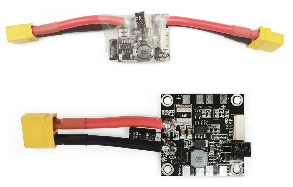
The PIX6 also supports power modules from other manufacturers, such as holybro_pm02d.
Recommended Accessories
GPS Modules
Radiolink manufactures a variety of high-performance GPS,Dual Anti-interference Technology Worry-free of UAV High-power Image Transmission, High-Voltage Lines, or Other Strong Signal Interference.
The PIX6 has 2 dedicated GPS ports, GPS1 and GPS2, each with a 6 pin connector.
Recommended modules include:
Serial Port Mapping
| UART | Device | Port |
|---|---|---|
| UART1 | /dev/ttyS0 | GPS1 |
| USART2 | /dev/ttyS1 | TELEM1 (flow control) |
| USART3 | /dev/ttyS2 | TELEM2 (flow control) |
| UART4 | /dev/ttyS3 | GPS2 |
| UART7 | /dev/ttyS4 | Debug Console |
| UART8 | /dev/ttyS5 | PX4IO |
Analog inputs
The Radiolink PIX6 has 3 analog inputs, one 6V tolerant and two 3.3V tolerant.
- ADC Pin12 -> ADC 6.6V Sense
- ADC Pin4 -> ADC IN1 3.3V Sense
- ADC Pin13 -> ADC IN2 3.3V Sense
Radio Control
A Radio Control (RC) system is required if you want to manually control your vehicle (PX4 does not require a radio system for autonomous flight modes).
You will need to select a compatible transmitter/receiver and then bind them so that they communicate (read the instructions that come with your specific transmitter/receiver).
- Spektrum/DSM receivers connect to the DSM/SBUS RC input.
- PPM or SBUS receivers connect to the RC IN input port.
- CRSF receiver must be wired to a spare port (UART) on the Flight Controller. Then you can bind the transmitter and receiver together.
CRSF Parameter Configuration
Find and set the following parameters:
Set RC_CRSF_PRT_CFG to the port that is connected to the CRSF receiver (such as
TELEM1).This configures the serial port to use the CRSF protocol. Note that some serial ports may already have a default serial port mapping or default MAVLink serial port mapping that you will have to un-map before you can assign the port to CRSF. For example, if you want to use
TELEM1orTELEM2you first need to modify MAV_0_CONFIG or MAV_1_CONFIG to stop setting those ports.There is no need to set the baud rate for the port, as this is configured by the driver.
Enable RC_CRSF_TEL_EN to activate Crossfire telemetry.
For more information about selecting a radio system, receiver compatibility, and binding your transmitter/receiver pair, see: Remote Control Transmitters & Receivers.