CUAV X25 EVO Wiring Quick Start
WARNING
PX4 does not manufacture this (or any) autopilot. Contact the manufacturer for hardware support or compliance issues.
This quick start guide shows how to power the X25 EVO flight controller and connect its most important peripherals.
INFO
The following flight controller models are applicable to this quick start guide. CUAV X25 SUPERCUAV X25 MEGA
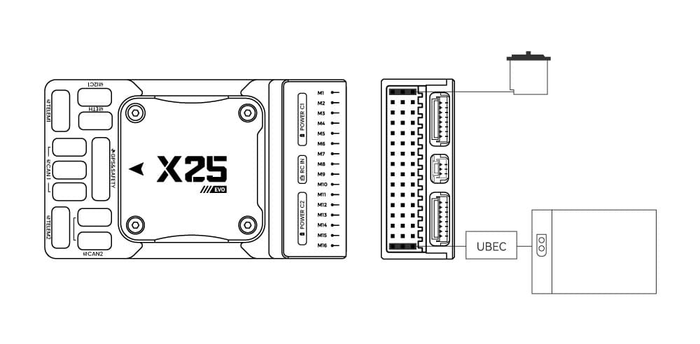
Wiring Chart Overview
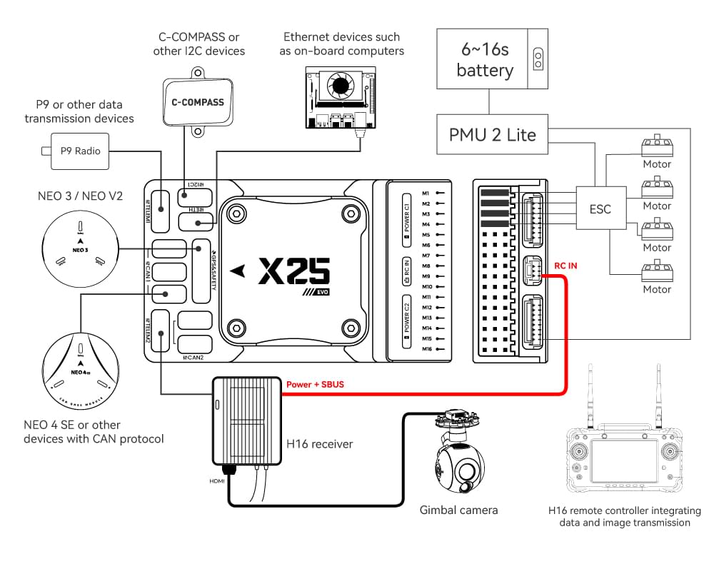
The image below shows how to connect the most important sensors and peripherals (except the motor and servo outputs). We'll go through each of these in detail in the following sections.
| Interface | Function |
|---|---|
| POWER C1/C2 | Connect the PMU2 Lite to this port; this port is used for connecting the DroneCAN power module |
| M1 ~ M16 | PWM signal output ports, usable for controlling motors or servos; support 3.3V/5V PWM configuration |
| RC IN | Connect remote controller receivers with one-way protocols (e.g., SBUS/DSM/PPM). Note: ELRS/CRSF receivers should be connected to any serial port, not RC IN |
| RSSI | For connecting signal strength feedback modules |
| GPS&SAFETY | Connect Neo-series GPS or C-RTK-series RTK; this port includes interfaces for GPS, safety switch, and buzzer |
| GPS2 | Usable for connecting additional GPS/RTK modules |
| DEBUG (DSU) | For FMU chip debugging and reading debug device information; with ArduPilot firmware, it can be configured for other serial port functions |
| ADC3V3 | For analog level signal detection; the maximum detectable level signal is 3.3V |
| ADC6V6 | For analog level signal detection; the maximum detectable level signal is 6.6V (PX4 is not supported.) |
| TF CARD | Insert an SD card here to enable log storage functionality |
| ETH | Ethernet port, usable for connecting Ethernet devices such as companion computers |
| I2C1/2/3 | Connect external I2C devices (e.g., external compasses) for communication between the controller and I2C devices |
| TELEM1/TELEM2 | Connect telemetry modules (for data transmission) to enable MAVLINK data interaction |
| CAN1/2 | For communication between the controller and DroneCAN devices (e.g., connecting NEO4 SE GPS) |
| TYPE C | USB port of the controller, usable for connecting to the ground station, flashing firmware, and other operations |
| SPI6 | SPI port for external expansion; generally not used |
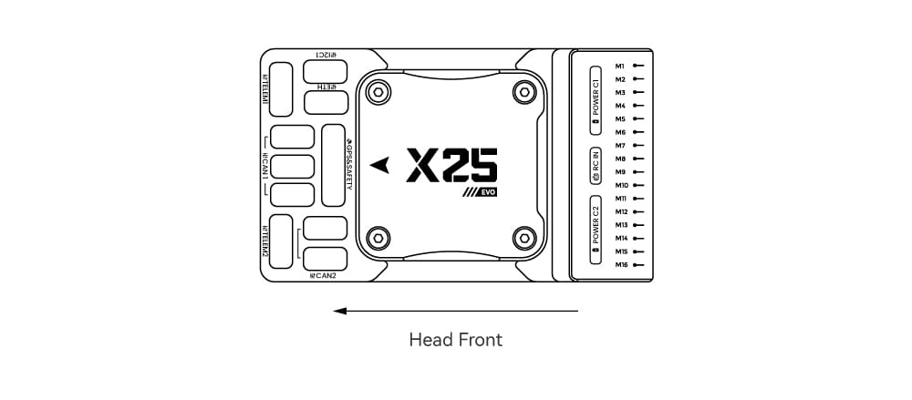
Vehicle Front
INFO
If the controller cannot be mounted in the recommended/default orientation (e.g. due to space constraints) you will need to configure the autopilot software with the orientation that you actually used: Flight Controller Orientation.
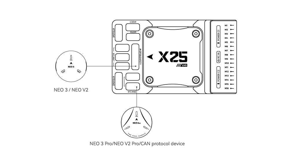
GPS + Compass + Buzzer + Safety Switch + LED
We recommend using a CAN GPS/RTK (such as Neo 4SE); simply connect it to the CAN 1 or CAN 2 port.
You can also use a standard GPS/RTK module(such as NEO3 GPS (10-pin connector)) by connecting it to the GPS&SAFETY port. Most commonly used GPS modules today integrate GPS, compass, safety switch, buzzer, and LED status light.
If you need to use assisted GPS, connect to the GPS2 port.
The GPS/compass should be mounted on the frame as far away from other electronics as possible (separating the compass from other electronics will reduce interference), with the direction markings towards the front of the vehicle (the arrow on the NEO GPS should match the arrow on the flight controller).
INFO
The GPS module's integrated safety switch is enabled by default (when enabled, PX4 will not let you arm the vehicle). To disable the safety, press and hold the safety switch for 1 second. You can press the safety switch again to enable safety and disarm the vehicle (this can be useful if, for whatever reason, you are unable to disarm the vehicle from your remote control or ground station).
Radio Control
A remote control (RC) radio system is required if you want to manually control your vehicle (PX4 does not require a radio system for autonomous flight modes).
You will need to select a compatible transmitter/receiver and then bind them so that they communicate (read the instructions that come with your specific transmitter/receiver).
Connection methods vary by remote controller and receiver type:
Android Remote Controllers
Take the H16 as an example:
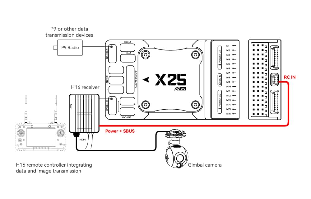
Connect TELEM1/TELEM2 to the UART0 port of the H16 remote controller, and link the H16’s SBUS pin to the RC IN port.
SBUS/DSM/PPM Protocol Receivers
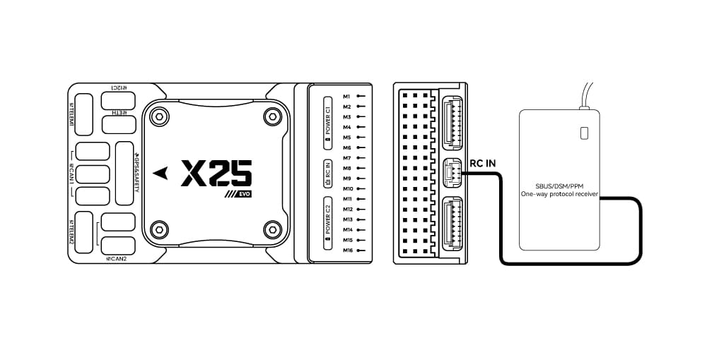
Use wires to connect the receiver to the RC IN port at the rear of the controller.
ELRS/CRSF Receivers
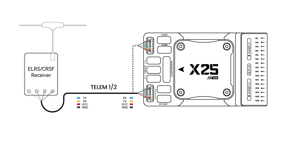
Connect the ELRS/CRSF receiver to any UART serial port of the X25 EVO (e.g., TELEM2).
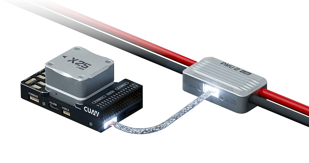
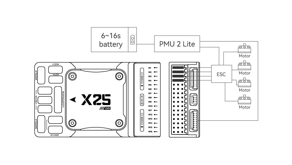
Power
The X25 EVO comes standard with the PMU2 Lite power module, which supports 20–70V input and can measure a maximum current of 220A. It can be directly connected to the Power C1/C2 port of the X25 EVO and is plug-and-play (no configuration required).
Telemetry (Radio) System
Telemetry system allows you to communicate with the unmanned system via ground station software, enabling you to monitor and control the UAV’s status during flight. Connect the on-board unit of the telemetry system to the TELEM1 or TELEM2 port.
You can also purchase telemetry radios from the CUAV store.
SD Card
SD cards are highly recommended as they are required for recording and analyzing flight details, running tasks and using UAVCAN bus hardware. An SD card is already installed on X25 EVO when it leaves the factory.
TIP
For more information see Basic Concepts > SD Cards (Removable Memory).
Motors/Servo
Motors/servos are connected to the M1~M16 ports in the order specified for your vehicle in the Airframe Reference.
Servo Power Supply
The X25 EVO does not supply power to servos. If you need to power servos:
- Connect a BEC to the positive and negative terminals of any column among M1 ~ M16 (the positive and negative terminals of M1 ~ M16 are interconnected).
- Then connect the servos to the same column.
INFO
The power rail voltage must be appropriate for the servo being used!
Other Peripherals
The wiring and configuration of optional/less common components is covered within the topics for individual peripherals.
Configuration
General configuration information is covered in: Autopilot Configuration.
QuadPlane-specific configuration is covered here: QuadPlane VTOL Configuration