VOLOLAND NarinFC-H7
PX4 v1.17WARNING
PX4 does not manufacture this (or any) autopilot. Contact the manufacturer for hardware support or compliance issues.
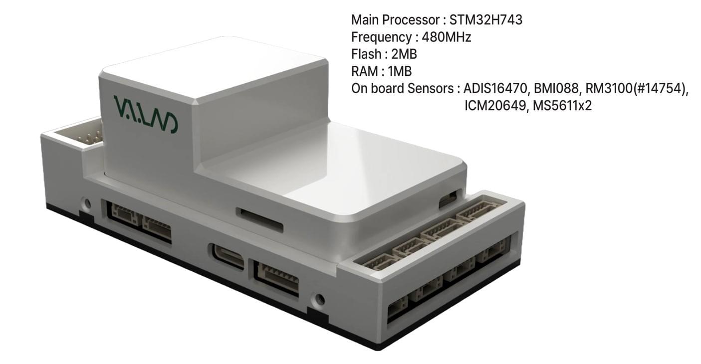
The NarinFC-H7 is an advanced flight controller produced by VOLOLAND Inc.. It uses a high-performance STM32H7 processor and integrates industrial-grade sensors for improved performance and reliability.
INFO
This flight controller is manufacturer supported.
Key Features
Processors & Sensors
- FMU Processor: STM32H743
- On-board sensors:
- Accelerometer/Gyroscope: ADIS16470
- Accelerometer/Gyroscope: ICM-20649
- Accelerometer/Gyroscope: BMI088
- Magnetometer: RM3100
- Barometer: MS5611 x2
Interfaces
- 14 PWM servo outputs
- Multiple RC inputs (SBUS / CPPM / DSM)
- Analog/PWM RSSI input
- 2 GPS ports (GPS and UART4)
- 4x I2C buses
- 2x CAN bus ports
- 2x Power ports
- 2x ADC ports
- 1x USB port
Electrical Data
- Power input: 4.3V ~ 5.4V
- USB input: 4.75V ~ 5.25V
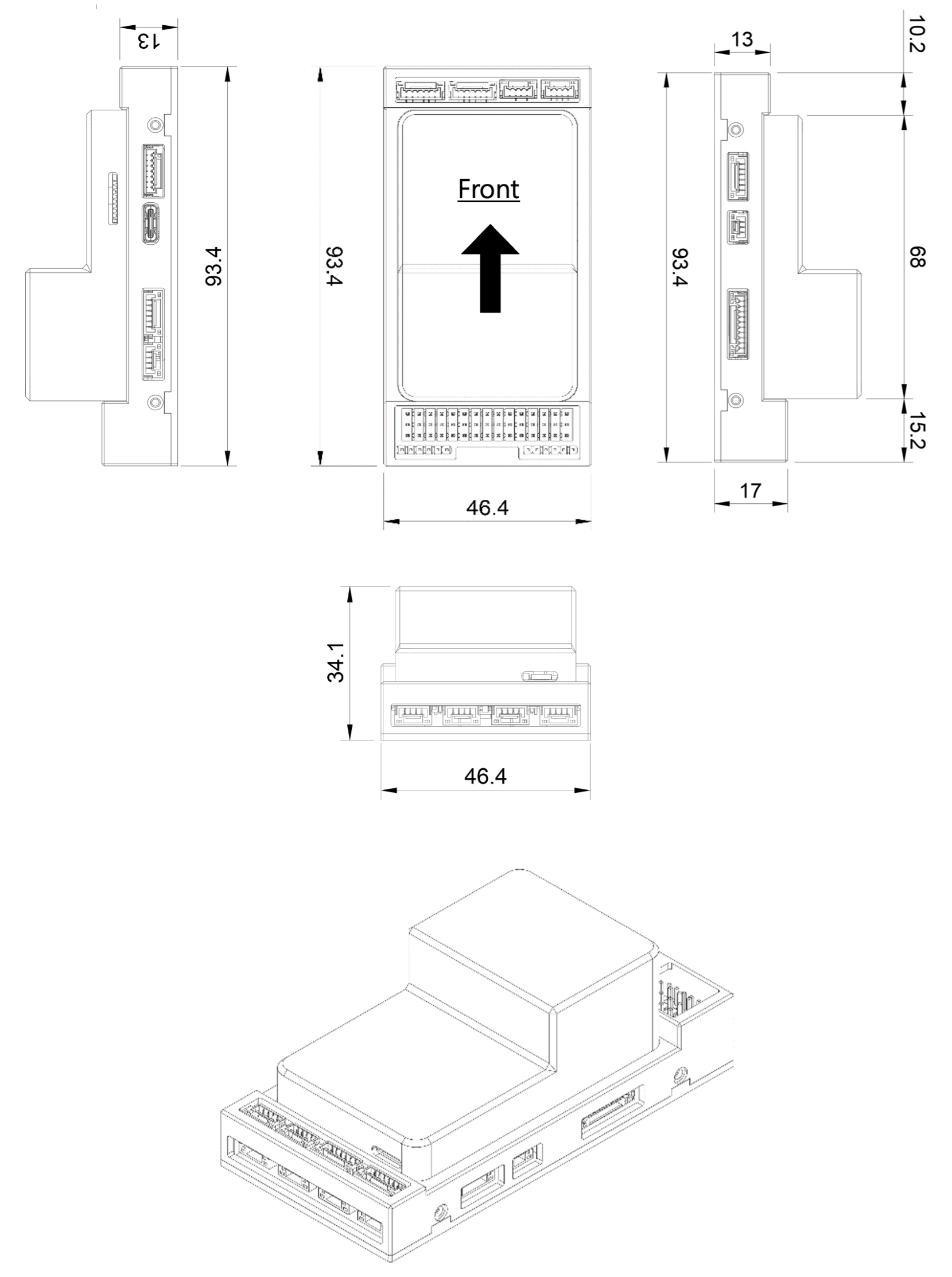
Mechanical Data
- Dimensions: 93.4 x 46.4 x 34.1 mm
- Weight: 106g
Where to Buy
Order from VOLOLAND Inc..
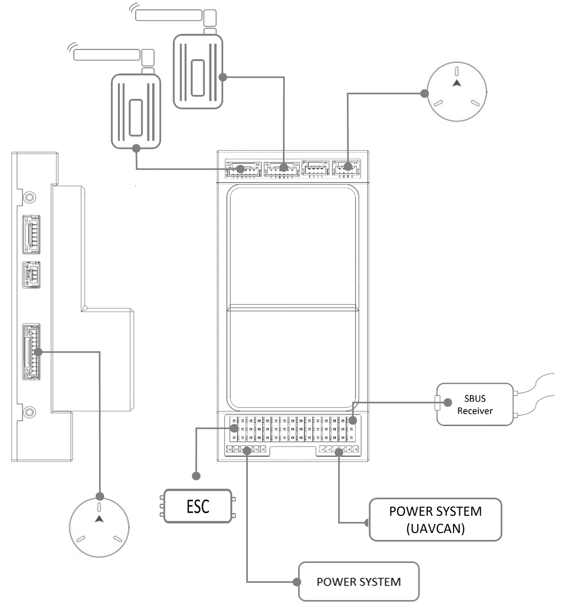
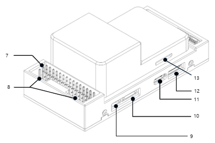
Connections
Dimensions
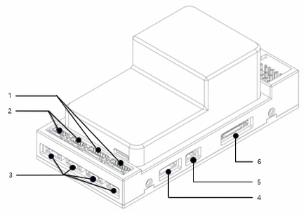
Pinouts
TELEM1 / TELEM2 Port
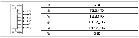
- JST GH 6P connector
CAN1 / CAN2 Port

- JST GH 4P connector
- Communication Protocol: UAVCAN v0 (default), UAVCAN v1 (limited support)
- Pin Configuration: CAN_H, CAN_L, VCC, GND
I2C1, I2C2, I2C3, I2C4 Port

- JST GH 4P connector
UART4 Port
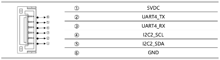
- JST GH 6P connector
RSSI Port

- RSSI input
GPS & Safety Port
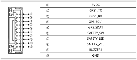
- JST GH 10P connector
PWM & RC_IN
The NarinFC-H7 supports up to 14 PWM outputs.
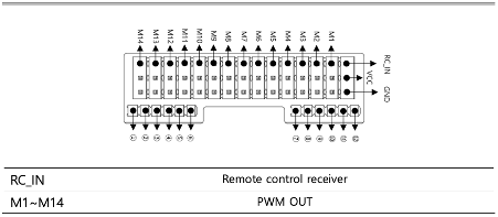
- 2.54mm pitch DuPont connector
- RC_IN: Remote control receiver input is wired directly to the FMU and is enabled via the
rc_inputdriver. Compatible with SBUS, CPPM, and DSM protocols.
Power Input
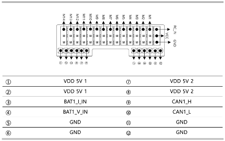
- 2mm pitch DuPont connector
ADC Port

DEBUG / UART7 Port
UART7 is labelled DEBUG RX/TX.
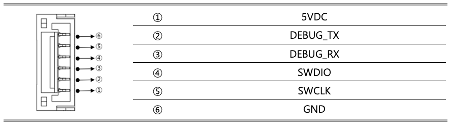
- JST GH 6P connector
USB Port
- USB-C
SPI Port
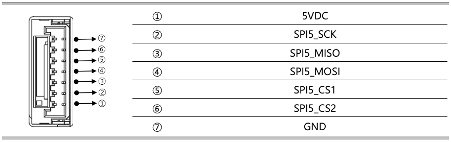
- JST GH 7P connector
Serial Port Mapping
| UART | Device | Port |
|---|---|---|
| USART1 | /dev/ttyS0 | GPS1 |
| USART2 | /dev/ttyS1 | TELEM1 |
| UART4 | /dev/ttyS2 | GPS2 |
| USART6 | /dev/ttyS3 | TELEM2 |
| UART8 | /dev/ttyS4 | User |
| UART7 | /dev/ttyS5 | Debug |
PWM Output
The NarinFC-H7 supports up to 14 PWM outputs. All outputs except M13 and M14 support DShot. Outputs 1-8 support Bi-Directional DShot.
The 14 PWM outputs are in 4 groups:
- Outputs 1, 2, 3, and 4 in group1
- Outputs 5, 6, 7, and 8 in group2
- Outputs 9, 10, 11, and 12 in group3
- Outputs 13 and 14 in group4
All outputs within the same group must use the same output rate and protocol.
Analog Inputs
The NarinFC-H7 has 2 user-accessible analog inputs:
- ADC Pin4 → SPARE1_ADC1 (6.6V tolerant)
- ADC Pin18 → SPARE2_ADC1 (3.3V tolerant)
Additional internal ADC channels:
- ADC Pin16 → BATT_VOLTAGE_SENS
- ADC Pin17 → BATT_CURRENT_SENS
- ADC Pin14 → BATT2_VOLTAGE_SENS
- ADC Pin2 → BATT2_CURRENT_SENS
- ADC Pin6 → RSSI_IN
- ADC Pin8 → VDD_5V_SENS
- ADC Pin11 → SCALED_V3V3
Building Firmware
TIP
Most users will not need to build this firmware! It is pre-built and automatically installed by QGroundControl when appropriate hardware is connected.
To build PX4 for this target:
make narinfc_h7_defaultSupported Platforms / Airframes
Any multicopter / airplane / rover or boat that can be controlled with normal RC servos or Futaba S-Bus servos. The complete set of supported configurations can be seen in the Airframes Reference.