CORVON 743v2
PX4 v1.18WARNING
PX4 does not manufacture this (or any) autopilot. Contact the manufacturer for hardware support or compliance issues.
The CORVON 743v2 is a flight controller designed by Feikong Technology Co., Ltd under the CORVON brand. It builds on the CORVON 743v1 platform with significantly upgraded sensor and connectivity options: dual high-grade IMUs (ICM-42688P + BMI088), a high-precision BMP581 barometer, a dedicated DJI O4 Air Unit connector, an onboard Bluetooth module with a ceramic antenna, and dual analog battery monitoring channels.
The board uses Pixhawk Autopilot Standard Connections.


INFO
This flight controller is manufacturer supported.
Key Features
- MCU: STM32H743VIH6 (32 Bit Arm® Cortex®-M7, 480 MHz, 2MB Flash, 1MB RAM, TFBGA100 package)
- IMU (Dual): TDK InvenSense ICM-42688P (primary) + Bosch BMI088 accel/gyro (secondary)
- Barometer: Bosch BMP581 (high-precision)
- Magnetometer: iSentek IST8310
- Interfaces:
- 8x UARTs (including dedicated DJI O4 and Bluetooth ports)
- 1x CAN (DroneCAN / UAVCAN)
- 1x external I²C (with isolated 5V supply)
- 1x dedicated RC Input (SBUS / CRSF / ELRS)
- 12x PWM outputs (M1–M10 DShot-capable, M11 / M12 standard PWM for servos)
- SDMMC1 4-bit Micro-SD slot (high-speed logging)
- Dedicated DJI O4 Air Unit connector
- Onboard Bluetooth module with ceramic antenna (UART8, MAVLink pre-configured)
- Power:
- Dual analog battery voltage/current channels (BAT1 via the
PWM4-in-1 ESC connector, BAT2 viaB2V/B2Ipads) - Voltage sensing up to 10S LiPo by default
- On-board BECs for peripheral power (consult manufacturer for exact rail specifications)
- Dual analog battery voltage/current channels (BAT1 via the
Where to Buy
Order from CORVON.
Physical / Mechanical
Refer to the manufacturer's datasheet for the latest mechanical drawing, mounting pattern, and weight specifications.
Specifications
Processors & Sensors
- FMU Processor: STM32H743VIH6
- 32 Bit Arm® Cortex®-M7, 480 MHz
- 2MB Flash, 1MB RAM
- TFBGA100 (8 × 8 mm) package
- On-board Sensors:
- Accel/Gyro 1: TDK InvenSense ICM-42688P (SPI3)
- Accel/Gyro 2: Bosch BMI088 (SPI3)
- Barometer: Bosch BMP581 (I²C2, address
0x46) - Compass: iSentek IST8310 (I²C2, address
0x0E)
Power Configuration
The board provides two independent analog battery monitoring channels:
- BAT1 - Battery voltage and current sensed from the
PWM4-in-1 ESC connector, onADC1_INP10(voltage) andADC1_INP11(current). - BAT2 - Auxiliary
B2V/B2Isolder pads for a second / redundant battery pack, sensed onADC1_INP4(voltage) andADC1_INP8(current).
Both channels feed PX4's standard analog battery driver with a default 21.2 voltage divider and 40 A/V current ratio, supporting up to 10S LiPo batteries out of the box.
INFO
The board does not expose the 5V rail / system_power sensing pins that PX4's commander power checks expect, so CBRK_SUPPLY_CHK (894281) is set by default to bypass the power supply and battery health checks used for arming and failsafe decisions. BAT1/BAT2 voltage and current monitoring is unaffected.
Connectors & Pinouts
The following image shows the physical connector and solder-pad layout, with the labels used in this document and in the firmware's default.px4board:
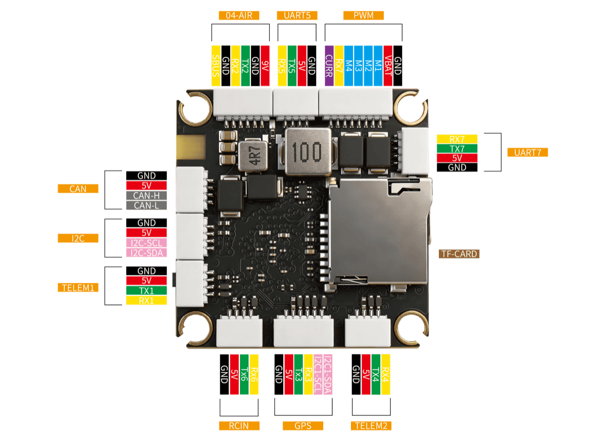
The board exposes the following connectors and solder pads:
TELEM1(4-pin) - primary MAVLink radio link04-AIR(6-pin) - DJI O4 Air Unit (Digital VTX with MSP DisplayPort)GPS(6-pin JST-GH) - UBX / NMEA GPS, with the external compass I²C bus broken out on the same connectorTELEM2(4-pin) - companion computer / secondary MAVLinkUART5(4-pin) - generic auxiliary UART breakoutRCIN(4-pin) - SBUS / CRSF / ELRS receiver inputUART7pads (TX7 / RX7) - ESC TelemetryCAN(4-pin) - FDCAN1 (DroneCAN / UAVCAN)I2C(4-pin) - external I²C, isolated 5V supply for short-circuit protectionPWM(8-pin) - 4-in-1 ESC connector (M1–M4 + power + ESC Telemetry)- Onboard Bluetooth module (UART8) with ceramic antenna - MAVLink pre-configured
SWD(4-pin) - hardware debug (SWCLK / SWDIO / 3V3 / GND)
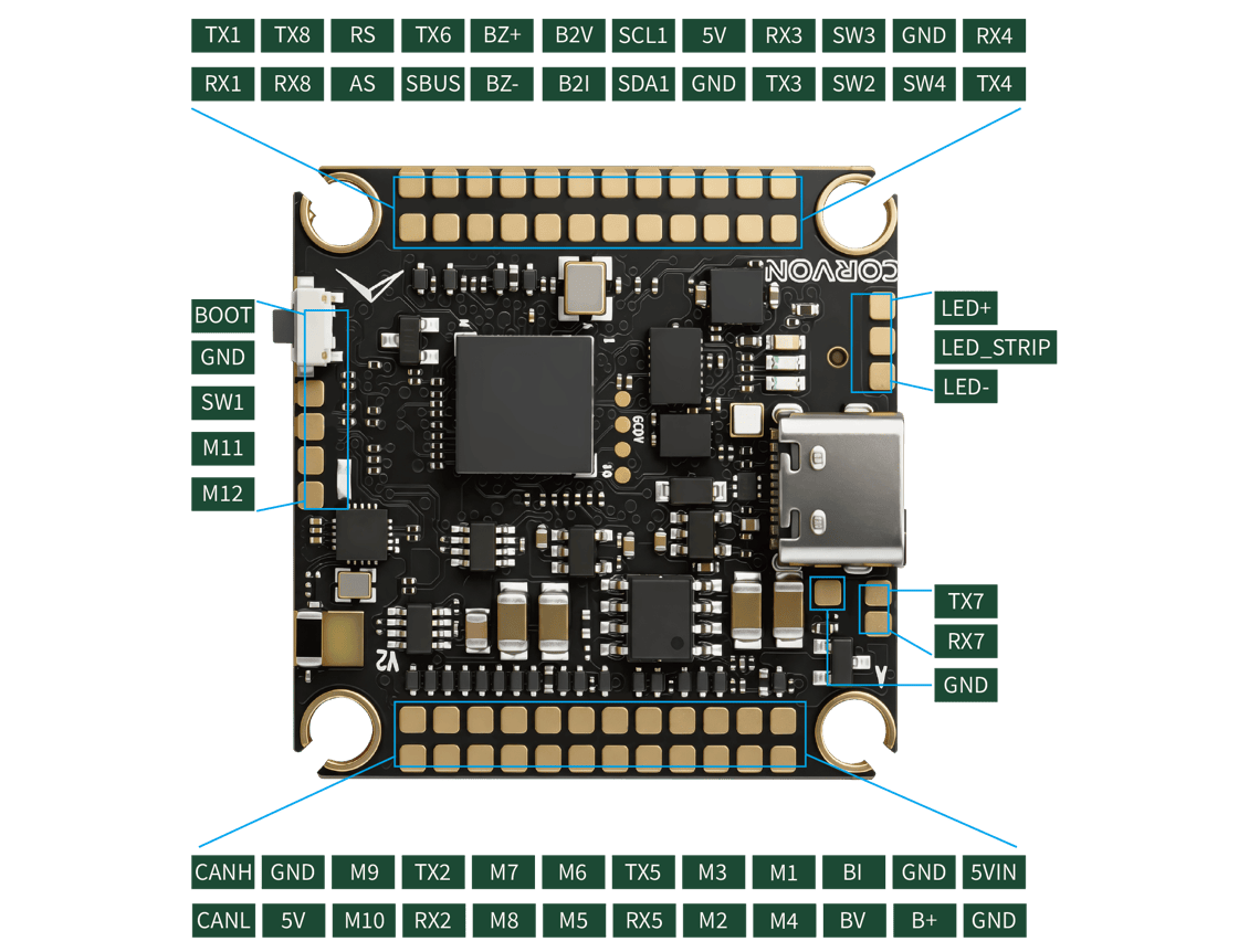
The next image shows the individual solder-pad signal assignments on both the top and bottom of the board for advanced wiring (GPIO breakouts, ADC pads, etc.):
Standard Serial Port Mapping
| Physical UART | PCB Silk Label | PX4 Slot (QGC) | Default Usage |
|---|---|---|---|
| USART1 | TELEM1 | TELEM 1 | MAVLink |
| USART2 | 04-AIR | - | DJI O4 Air Unit (MSP DisplayPort) |
| USART3 | GPS | GPS 1 | GPS (plus external compass on shared I²C) |
| UART4 | TELEM2 | TELEM 2 | MAVLink (Companion Link) |
| UART5 | UART5 | TELEM 3 | User Auxiliary |
| USART6 | RCIN | RC | RC Input (SBUS / CRSF / ELRS) |
| UART7 | UART7 | UART 6 | ESC Telemetry |
| UART8 | (onboard BT) | TELEM 4 | Bluetooth MAVLink @ 115200 (pre-configured) |
TIP
The silk labels UART5 and UART7 on the PCB refer to the STM32H743's physical UART numbers. In QGroundControl these ports appear as TELEM 3 and UART 6 respectively, because of PX4's internal serial-slot abstraction. When assigning a service in QGroundControl, look up the silk label in the PCB Silk Label column to find the corresponding PX4 Slot name.
Debug Port
The board features a 4-pin SWD Debug interface (SWCLK / SWDIO / 3V3 / GND) for hardware debugging. There is no dedicated NSH console UART; the NSH console is exposed over USB CDC out of the box and is available via QGroundControl's MAVLink Console.
RC Input
RC Input is mapped to USART6 through the dedicated RCIN connector.
Both the receive line (RX6, internally invert-capable for SBUS) and the transmit line (TX6) are broken out, so the port supports:
- Single-wire SBUS (inverted)
- TBS Crossfire (CRSF)
- ExpressLRS (ELRS)
- FPort, Spektrum DSM, Graupner SUMD, and others
Configure the receiver protocol with the relevant RC_*_PRT_CFG parameter from QGroundControl, pointing it at the RC slot.
PWM Output Groups
The 12 PWM outputs are organized into four timer groups. Channels in the same group must use the same output rate and DShot mode:
| Group | Timer | Channels | Default Protocol |
|---|---|---|---|
| 1 | TIM1 | M1–M4 | DShot600 |
| 2 | TIM3 | M5–M6 | DShot600 |
| 3 | TIM4 | M7–M10 | DShot600 |
| 4 | TIM12 | M11–M12 | PWM only (servo / gimbal) |
M1–M9 support BDShot telemetry readback; M10 is DShot-only because TIM4_CH4 has no input-capture DMA channel on STM32H7. Bidirectional DShot can be enabled by setting PWM_MAIN_TIM0..2 to a BDShot value (-6 BDShot600, -7 BDShot300, -8 BDShot150) in QGroundControl.
Channels within the same group need to use the same output rate. If any channel in a group uses DShot then all channels in the group need to use DShot.
Bluetooth Telemetry (Pre-configured)
The board has an onboard Bluetooth module with a ceramic antenna, wired internally to UART8. The factory firmware pre-binds MAVLink instance 2 to this port at 115200 baud with no flow control, so the link works out of the box: just pair the board from a phone or tablet GCS - no QGroundControl parameter changes required.
Building / Loading Firmware
TIP
Most users will not need to build this firmware (from PX4 v1.18). It is pre-built and automatically installed by QGroundControl when appropriate hardware is connected.
To build PX4 for this target from source:
make corvon_743v2_defaultInitial firmware flashing can be done over USB via QGroundControl. The bootloader status follows the standard generic PX4 LED indications (Red = Bootloader / Error, Blue = Active / Activity, Green = Powered).