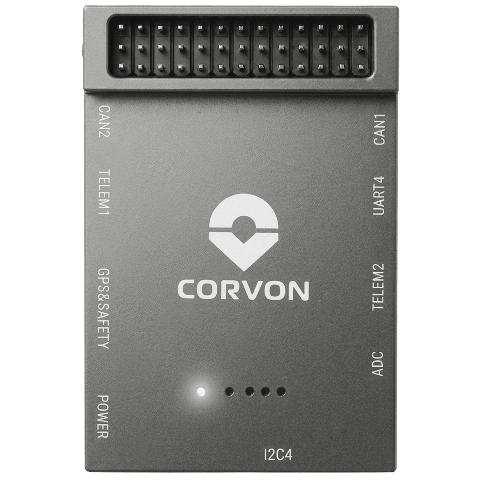
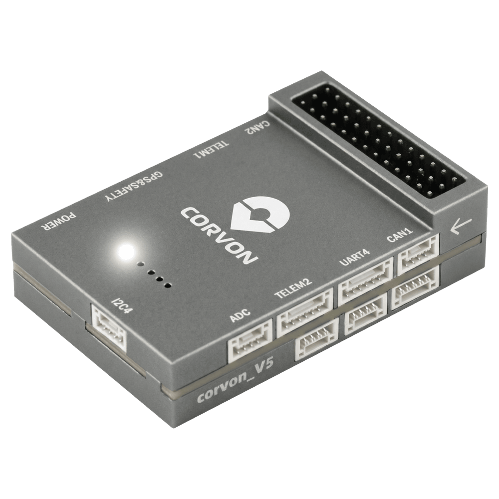
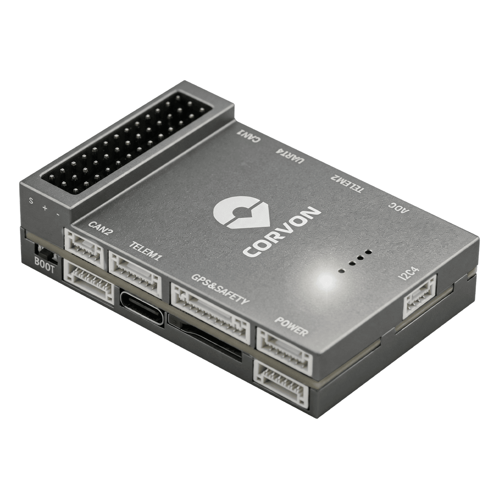
CORVON V5 Autopilot
PX4 v1.18WARNING
PX4 does not manufacture this (or any) autopilot. Contact the manufacturer for hardware support or compliance issues.
The CORVON V5 is based on the Pixhawk FMUv5 design standard and runs PX4 on NuttX.
INFO
This flight controller is manufacturer supported.
Specifications
Main FMU Processor: STM32F765IIK
- 32 Bit Arm® Cortex®-M7, 216MHz, 2MB memory, 512KB RAM
On-board sensors:
- Accel/Gyro: ICM-20689
- Accel/Gyro: ICM-20602
- Accel/Gyro: BMI088
- Magnetometer: IST8310
- Barometer: MS5611
Interfaces:
- 8 PWM outputs
- 3 dedicated PWM/Capture inputs on FMU
- Dedicated R/C input for CPPM
- Dedicated R/C input for Spektrum / DSM and S.Bus
- Analog / PWM RSSI input
- 4 general purpose serial ports
- 3 I2C ports
- 4 SPI buses
- 2 CAN Buses
- Analog inputs for voltage / current of battery
- 2 additional analog inputs
- Supports nARMED
Power System:
- Power Brick Input: 4.75~5.5V
- USB-C Power Input: 4.75~5.25V
Weight and Dimensions:
- Weight: 42.1g
- Dimensions: 61.2 x 40 x 15.9mm
Other Characteristics:
- Operating temperature: -20 ~ 85°C (Measured value)
Where to Buy
Connectors and Interfaces
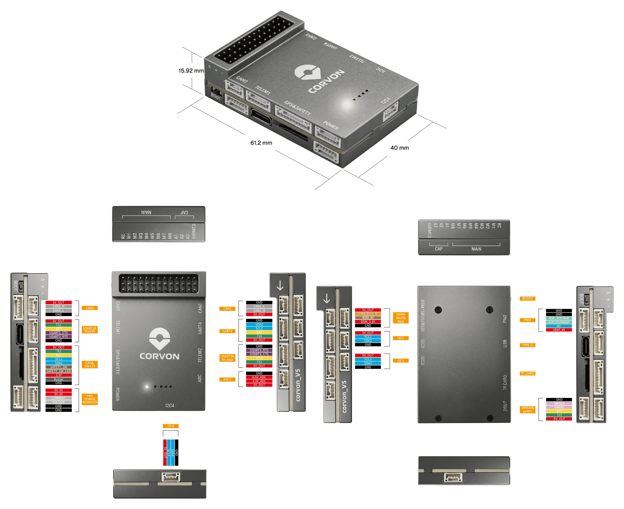
Pinouts
Download Corvon V5 pinouts from here: corvon_v5_pinout.xlsx
Serial Port Mapping
| UART | Device | Port | Flow Control |
|---|---|---|---|
| USART1 | /dev/ttyS0 | GPS | - |
| USART2 | /dev/ttyS1 | TELEM1 | Yes |
| USART3 | /dev/ttyS2 | TELEM2 | Yes |
| UART4 | /dev/ttyS3 | TELEM4 | - |
| USART6 | /dev/ttyS4 | RC | - |
| UART7 | /dev/ttyS5 | Debug Console | - |
| UART8 | /dev/ttyS6 | Reserved for optional onboard RTK module | - |
INFO
UART8 is reserved for an optional onboard UM982 module footprint and is not intended for general external use.
Radio Control
A remote control (RC) radio system is required if you want to manually control your vehicle (PX4 does not require a radio system for autonomous flight modes). You will need to select a compatible transmitter/receiver and then bind them so that they communicate (read the instructions that come with your specific transmitter/receiver).
The ports and supported protocols are:
DSM/SBUS/RSSI(FMU): SBUS, DSM/DSMX, ST24, SUMD, CRSF, and GHST receiversRC: PPM
For PPM and S.Bus receivers, a single signal wire carries all channels. If your receiver outputs individual PWM signals (one wire per channel) it must be connected via a PPM encoder.
GPS & Compass
PX4 supports GPS modules connected to the GPS port(s) listed below. The module should be mounted on the frame as far away from other electronics as possible, with the direction marker pointing towards the front of the vehicle.
The GPS ports are:
GPS&SAFETY(FMU): 10-pin JST GH (Pixhawk Connector Standard) — GPS, compass (I2C), safety switch, buzzer, LED.
The GPS module's integrated safety switch is enabled by default (when enabled, PX4 will not let you arm the vehicle). To disable the safety switch press and hold it for 1 second. You can press the safety switch again to enable safety and disarm the vehicle.
PWM Outputs
This flight controller supports up to 8 FMU PWM outputs (MAIN).
DShot is not supported.
The 8 outputs are in 3 groups:
- Outputs 1-4 in group1 (Timer1)
- Outputs 5-6 in group2 (Timer4)
- Outputs 7-8 in group3 (Timer12)
All outputs within the same group must use the same output protocol and rate.
Debug Port
The PX4 System Console and SWD interface operate on the FMU Debug port (DSU7).
The debug port (DSU7) has the following pinout:
| Pin | Signal | Volt |
|---|---|---|
| 1 | GND | GND |
| 2 | FMU_SWCLK | +3.3V |
| 3 | FMU_SWDIO | +3.3V |
| 4 | DEBUG RX | +3.3V |
| 5 | DEBUG TX | +3.3V |
| 6 | 5V+ | +5V |
WARNING
The 5V+ pin (6) provides 5V, but the CPU logic runs at 3.3V!
Some JTAG/SWD adapters (like SEGGER J-Link) may use the Vref voltage pin to set the logic level on the SWD data lines. Connecting 5V to the adapter's Vtref can damage the CPU. For a direct connection to a Segger Jlink, we recommend you use a 3.3V source to provide Vtref to the JTAG adapter (i.e. providing 3.3V and NOT 5V).
Voltage Ratings
CORVON V5 must be powered from the POWER connector during flight, and may also be powered from USB for bench testing.
- POWER input: 4.75~5.5V
- USB input: 4.75~5.25V
The PM2 connector cannot power the flight controller. On PX4, do not use this interface.
Building Firmware
To build PX4 for this target:
make corvon_v5_defaultInstalling PX4 Firmware
The firmware can be installed in any of the normal ways:
Build and upload the source
shmake corvon_v5_default uploadLoad the firmware using QGroundControl. You can use either pre-built firmware or your own custom firmware.
INFO
If this target is not listed in QGroundControl, build and upload from source or load a custom firmware file (see Installing PX4 Main, Beta or Custom Firmware).
Supported Platforms / Airframes
Any multicopter / airplane / rover or boat that can be controlled with normal RC servos or Futaba S-Bus servos. The complete set of supported configurations can be seen in the Airframes Reference.
Images