
Internal Combustion Engines (ICE)
PX4 can operate a single spark-ignition internal combustion engine (ICE) — a petrol/nitro two- or four-stroke engine — as the propulsion system of a fixed-wing, VTOL, or helicopter vehicle.
Unlike an electric motor, an engine cannot simply be commanded to a thrust value: it has to be started (choke, ignition, electric starter), it can die in flight and need restarting, and it must be kept above a minimum idle speed to keep running at all. The internal_combustion_engine_control module implements this logic as a state machine that drives four dedicated actuator outputs and closes the loop on a measured engine speed (RPM).
WARNING
A running combustion engine with a propeller attached is dangerous. The engine can be commanded to start automatically (for example on arming, or on a VTOL transition to fixed-wing), and the starter motor will crank the propeller without further warning.
- Always do your first bench tests with the propeller removed.
- For continuous operation without a propeller, a flywheel is recommended.
- Keep clear of the propeller arc whenever the vehicle is powered.
- Verify that the engine stop functionality (ignition off, choke closed) reliably stops the engine before you rely on it.
Hardware Requirements
Throttle servo connected to a PWM/AUX output.
Ignition cut on an output, typically through a relay or opto-isolated switch that shorts or interrupts the ignition circuit. Optional.
Choke servo on an output (optional if the engine has no choke, or an automatic one — set ICE_CHOKE_ST_DUR to
0and leave the function unassigned).Electric starter on an output, typically through a relay or an ESC driving the starter motor. Optionally, the engine can also be hand-started.
RPM sensor feeding the
RPM Inputfunction on a timer-capture-capable PWM pin, for example a Hall-effect or optical sensor on the crankshaft, or an ignition-pulse pickup.Many engines have a built-in spark-timing sensor that can be used for this. If yours does not, see Tachometers for other options.
WARNING
RPM feedback is required. The state machine only leaves Starting for Running once it sees a measured engine speed above ICE_MIN_RUN_RPM. Without a working RPM sensor the module will exhaust its start attempts and latch into the Fault state.
Firmware Configuration
The module and the RPM capture driver are not in the default builds. Add them to the board configuration for your flight controller:
CONFIG_MODULES_INTERNAL_COMBUSTION_ENGINE_CONTROL=y
CONFIG_DRIVERS_RPM_CAPTURE=y
Both can also be enabled interactively with make <target> boardconfig, under modules and drivers respectively.
Parameter Setup
Set the following and reboot:
- ICE_EN to
Enabled. The startup script only starts the module if this is set. - RPM_CAP_ENABLE to
Enabled. - RPM_PULS_PER_REV to the number of sensor pulses per crankshaft revolution (for example
2for a two-magnet setup, or1for a single ignition pulse per revolution on a two-stroke).
Then work through the remaining ICE_* parameters:
- Actuator Configuration — wire up the engine outputs.
- Start/Stop Command Source — choose what commands the engine on and off.
- Idle RPM Governor — set up and tune closed-loop idle, and the
ICE_IDLE_*parameters. - Parameter Reference — the full list, including the start sequence timing.
Actuator Configuration
Assign the four engine functions and the RPM input in Actuator Configuration, for example:
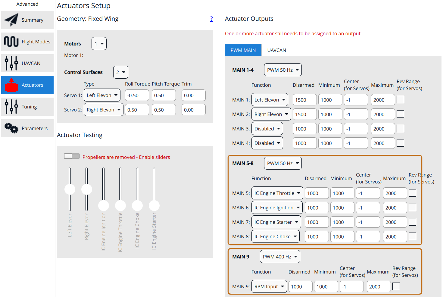
Each setpoint is in the range [0, 1] and is mapped to the [-1, 1] servo range before being scaled to the output's Minimum/Maximum values. In other words, a setpoint of 0 produces the configured Minimum output and 1 produces the configured Maximum output (or the reverse, if Rev Range is ticked).
INFO
When the engine is commanded off, the throttle setpoint is NAN, which by definition drives the output to its configured Disarmed value rather than to Minimum. This lets you park the throttle servo at an idle-stop position that is different from the closed-throttle position used to switch off the engine.
The throttle output also goes to Disarmed while the engine is running if the idle governor is disabled and the throttle demand drops to near zero (the fixed-wing controller stops the motor below 2% thrust).
Points to note when setting the values:
IC Engine Throttleuses Minimum for closed throttle and Maximum for full throttle. Setting Disarmed to a value other than Minimum parks the servo at an idle stop when the engine is off, rather than at closed throttle.IC Engine Chokeuses Minimum for choke open and Maximum for choke closed; tick Rev Range if the servo linkage is inverted.IC Engine IgnitionandIC Engine Starterbehave as on/off outputs: Minimum is "off" and Maximum is "on". Set both values so that the relay switches reliably, and make sure Disarmed corresponds to ignition off and starter off.RPM Inputmust be on a channel that supports timer capture on your board.
TIP
In the example above the Actuators tab stays red in the sidebar, and the page shows "One or more actuator still needs to be assigned to an output". This is expected for an engine setup and does not stop the engine from running: the airframe's Motor 1 slot is deliberately left unassigned, because the throttle reaches the servo through IC Engine Throttle instead — see How It Works.
WARNING
While the vehicle is disarmed, every output — including ignition, choke, and starter — is held at its Disarmed value, regardless of what the module commands. The engine can only be commanded when armed or prearmed.
Whether prearming happens at all is set by COM_PREARM_MODE, which matters if you want to start the engine before arming (for example from an AUX switch, see Start/Stop Command Source):
COM_PREARM_MODE | Effect on the engine outputs |
|---|---|
Disabled (default) | Never prearms, so the outputs stay at their Disarmed values until the vehicle is armed. |
Safety button | Outputs become live once the safety switch is released. Has no effect on boards that have no safety button — prearm then never engages. |
Always | Outputs become live 5 s after boot. |
WARNING
With Always the ignition, choke, and starter outputs are live shortly after power-up, before any arming check has run. The engine can be commanded to crank on a vehicle that was never armed, so treat the propeller as live whenever the vehicle is powered.
Start/Stop Command Source
ICE_ON_SOURCE selects what asks for the engine to run:
| Value | Engine is requested on when |
|---|---|
On arming - disarming (0) | The vehicle is armed. This is the default. |
Aux1 (1) | The AUX1 manual control channel is above 0.5; requested off when it goes below -0.5. Map a switch to it with RC_MAP_AUX1. |
Aux2 (2) | As above, using AUX2 and RC_MAP_AUX2. |
On Vtol Transitions (3) | The vehicle is in fixed-wing mode or transitioning to fixed-wing. Use this on a hybrid VTOL where the engine only drives the pusher/forward propeller. |
INFO
For the AUX sources, values between -0.5 and 0.5 leave the request unchanged. This dead zone means a three-position switch has a middle position that does not change the engine state, and it prevents a channel that is momentarily centred (or lost and defaulted to zero) from cutting the engine.
Idle RPM Governor
Left at a fixed low throttle, an engine tends either to die or to sit at an unpredictable idle speed that depends on temperature, air density, and mixture. The idle governor closes the loop on measured RPM whenever the throttle demand is low, keeping the engine alive and ready to accelerate.
It is enabled by setting ICE_IDLE_RPM to a non-zero idle speed. When enabled, the Running state has two sub-states, reported in InternalCombustionEngineStatus.substate:
Run— the throttle demand from allocation is passed straight through.Idle— the throttle output is produced by the governor instead.
The module enters Idle when the throttle demand drops below 2% (or becomes invalid, i.e. the vehicle is disarmed), or whenever the measured RPM falls below the idle setpoint. The second condition is what catches a sagging engine: even at high commanded throttle, if the engine is being dragged below its idle speed the governor takes over and pushes the throttle to recover it. It leaves Idle again as soon as the throttle demand exceeds the governor's current output, so the handover happens without a step in the output.
Control Structure
The governor is a feed-forward plus PI controller with output clamped to [0, 1]:
throttle = ICE_IDLE_THR_FF + P · e + ∫ I · e dt
       e = ICE_IDLE_RPM − rpm_estimate
       P = ICE_IDLE_RPM_P · 1e-3
       I = ICE_IDLE_RPM_I · 1e-3
The 1e-3 scaling is what makes the gains convenient to reason about:
- ICE_IDLE_RPM_P is the normalised throttle added per 1000 RPM of error.
ICE_IDLE_RPM_P = 1means an engine running 500 RPM slow gets+0.5throttle. - ICE_IDLE_RPM_I is the normalised throttle added per 1000 RPM·s of accumulated error.
ICE_IDLE_RPM_I = 1means a steady 100 RPM error winds the output up by0.1every second. - ICE_IDLE_THR_FF is the throttle that holds the idle speed on its own, so the PI terms only have to correct for the difference. It is applied as a constant offset whenever the governor is active.
The integrator is limited to ±1 and uses conditional integration: it stops winding up in whichever direction is already driving the output into saturation. It is reset to zero every time the engine reaches Running, so a start never inherits wind-up from a previous run.
Tuning Procedure
Do this on the ground, with the propeller removed or the vehicle firmly restrained, and with the engine warm.
- Find the idle speed. Pick the ICE_IDLE_RPM you want — low enough not to produce useful thrust, high enough that the engine runs smoothly and can accelerate without hesitating. The engine's specification or a hand-throttled test is the starting point.
- Find the feed-forward. With the governor still off (
ICE_IDLE_RPM = 0), start the engine and hold it at that RPM with the throttle stick in a manual mode. Read the commanded throttle off the log (internal_combustion_engine_control.throttle_control), set ICE_IDLE_THR_FF to it, and setICE_IDLE_RPMto the target. - Verify feed-forward only. With both gains still at
0, restart and let the engine idle. It should settle near the setpoint. A large steady offset means the feed-forward is wrong — correct it before adding gains, because the PI terms are only meant to trim. - Add proportional gain. Raise ICE_IDLE_RPM_P in steps (
0.2is a reasonable first step) until the engine recovers briskly when you disturb it — for example by briefly blipping the throttle up and releasing it. Back off as soon as you see the RPM hunting or the throttle oscillating. - Add integral gain. Raise ICE_IDLE_RPM_I just enough to remove any remaining steady-state RPM offset within a few seconds. Too much integral shows up as a slow oscillation around the setpoint.
- Check the handover. Sweep the throttle demand up and back down through the idle point and confirm there is no jump or dead spot as the sub-state switches between
IdleandRun.
The signals to look at in the flight log:
| Signal | Use |
|---|---|
rpm.rpm_estimate | Measured engine speed — compare against ICE_IDLE_RPM. |
internal_combustion_engine_control.throttle_control | Throttle actually commanded, after the governor and the slew rate limit. |
internal_combustion_engine_status.substate | Whether the governor is active (1 = Idle). |
internal_combustion_engine_status.pid_idle_rpm_integral | Integrator state. Parked at ±1 means it is saturated and the feed-forward is far off. |
internal_combustion_engine_status.state | State machine state — reveals unnoticed restarts. |
Both internal_combustion_engine_* topics are logged when the module is running.
INFO
rpm_capture low-pass filters the RPM estimate with a 0.5 s time constant. That lag is part of the loop you are tuning and puts a practical ceiling on how high the gains can go before the governor starts hunting.
Parameter Reference
| Parameter | Unit | Default | Description |
|---|---|---|---|
| ICE_EN | — | 0 | Start the ICE control module. Requires a reboot. |
| ICE_ON_SOURCE | — | 0 | What requests the engine on/off: arming, AUX1, AUX2, or VTOL transitions. |
| ICE_MIN_RUN_RPM | rpm | 2000 | RPM above which the engine counts as running. |
| ICE_IGN_DELAY | s | 0 | Delay between switching on the ignition and engaging the starter. |
| ICE_CHOKE_ST_DUR | s | 5 | How long the choke stays closed on the first start attempt. |
| ICE_STRT_DUR | s | 5 | Cranking time per attempt after the choke opens, before declaring a timeout. |
| ICE_STRT_THR | norm | 0.1 | Throttle held during choking and cranking. |
| ICE_STRT_ATTEMPT | — | 3 | Start attempts before entering Fault. 0 means a single attempt. |
| ICE_RUN_FAULT_D | — | 1 | Detect an engine stop while running and attempt a restart. |
| ICE_STOP_CHOKE | — | 1 | Close the choke while the engine is stopped or in fault. |
| ICE_THR_SLEW | 1/s | 0.5 | Maximum rate of change of the throttle output. |
| ICE_IDLE_RPM | rpm | 0 | Idle RPM setpoint. 0 disables the idle governor. |
| ICE_IDLE_THR_FF | norm | 0 | Feed-forward throttle for the idle governor. |
| ICE_IDLE_RPM_P | — | 0 | Idle governor proportional gain, per 1000 RPM of error. |
| ICE_IDLE_RPM_I | — | 0 | Idle governor integral gain, per 1000 RPM·s of error. |
Troubleshooting
| Symptom | Likely cause |
|---|---|
Nothing happens at all; internal_combustion_engine_control status reports the module is not running | ICE_EN is not set, or the module is not in the firmware. Check the build configuration and reboot. |
The engine runs but the state machine goes to Fault | The RPM sensor is not working or is misconfigured. Check RPM_CAP_ENABLE, RPM_PULS_PER_REV, and that the sensor is on a capture-capable pin; compare rpm.rpm_estimate against a hand tachometer. |
| Outputs never move even though the state machine advances | The vehicle is disarmed and not prearmed, so outputs are held at their Disarmed values. See the note above on COM_PREARM_MODE. |
| The starter cranks but the engine never fires | There may be no fuel in the engine yet. Closing the choke is what draws fuel in, so a dry engine needs a longer priming window — increase ICE_CHOKE_ST_DUR. Also check the cranking time (ICE_STRT_DUR) and the start throttle (ICE_STRT_THR), and note that too much choke floods the engine. |
The engine fires and then dies just after Starting finishes | No idle governor. Set up the idle governor; with ICE_IDLE_RPM = 0 there is nothing holding the engine up when the throttle demand is zero. |
Repeated in-air restarts logged as IC engine fault detected | ICE_MIN_RUN_RPM is set too close to the actual idle speed, so normal idle dips read as an engine stop. Raise the idle setpoint or lower the threshold. |
| The engine bogs down or stalls on throttle up | ICE_THR_SLEW is too high for the engine. Reduce it so the throttle opens more gradually. |
Developer Information
How It Works
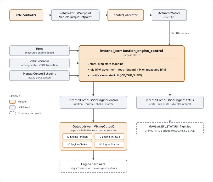
The module sits between the control allocator and the outputs:
- It takes the throttle demand from
actuator_motors.control[0], i.e. the thrust that allocation computed forMotor 1.INFO
The engine takes its throttle from whichever rotor the airframe geometry defines as
Motor 1(rotor 0,CA_ROTOR0_*), so you must set up the geometry with the engine as rotor 0. On a standard VTOL, this means making the pusher rotor 0 rather than the last rotor. You do not need to (and should not) assign an output for theMotor 1function. - It takes the on/off request from VehicleStatus (arming state, or the VTOL transition) or from ManualControlSetpoint (the AUX channels), depending on ICE_ON_SOURCE.
- It runs the start/stop state machine and publishes InternalCombustionEngineControl with the setpoints for ignition, throttle, choke, and starter.
- The mixer maps those four fields to the four
IC Engine *output functions, which is where you wire the engine hardware. - It subscribes to Rpm to know whether the engine is actually turning, and publishes InternalCombustionEngineStatus with the current state.
The module runs at 50 Hz.
Output Functions
| Output function | Field in InternalCombustionEngineControl | Meaning |
|---|---|---|
IC Engine Ignition | ignition_on | Spark/ignition enable. false cuts the spark and stops the engine (optional: many engine spark boxes always run when powered). |
IC Engine Throttle | throttle_control | Throttle servo setpoint, 0…1. NAN while the engine is commanded off. |
IC Engine Choke | choke_control | Choke servo setpoint, 0…1, where 1 is fully closed (richest mixture). Optional actuator. |
IC Engine Starter | starter_engine_control | Electric starter motor setpoint, 0…1. Optional actuator: the engine can also be hand-started. |
State Machine
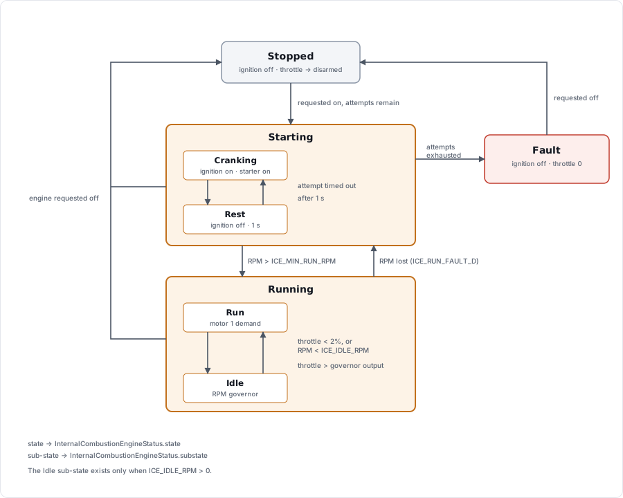
The module has four states, reported in InternalCombustionEngineStatus.state:
| State | Ignition | Throttle | Choke | Starter |
|---|---|---|---|---|
Stopped | off | NAN (→ Disarmed value) | ICE_STOP_CHOKE ? 1 : 0 | 0 |
Starting | on | ICE_STRT_THR | see start sequence | see start sequence |
Running | on | motor 1 demand, or idle governor output | 0 | 0 |
Fault | off | 0 | ICE_STOP_CHOKE ? 1 : 0 | 0 |
Transitions:
Stopped→Startingwhen the engine is requested on and the start attempt budget is not exhausted.Starting→Runningas soon as the measured RPM exceeds ICE_MIN_RUN_RPM. This can happen part way through an attempt.Starting→Faultwhen all attempts have been used without the engine coming up.Running→Startingif the RPM drops back below the threshold and ICE_RUN_FAULT_D is enabled — this is the automatic in-air restart. AnIC engine fault detectedevent is emitted.- Any state →
Stoppedwhen the engine is requested off. This also resets the attempt counter, so switching the request off and on again is the way to clear aFault.
Both Starting and Running have sub-states, reported in InternalCombustionEngineStatus.substate. Starting alternates between cranking and a one-second rest between attempts (see Start Sequence), and Running switches between passing the throttle demand straight through and running the idle governor.
INFO
The throttle setpoint is rate limited by ICE_THR_SLEW in all states, which protects the engine from abrupt throttle steps that would make it bog down or stall. The limit does not apply to the NAN used in Stopped; the slew state is reset to zero instead, so the next start ramps up from closed throttle.
Start Sequence
One start attempt runs the following timeline, measured from entry into the attempt:
| From | To | Ignition | Choke | Starter | Throttle |
|---|---|---|---|---|---|
0 | ICE_IGN_DELAY | on | 1 | 0 | ICE_STRT_THR |
ICE_IGN_DELAY | ICE_IGN_DELAY + ICE_CHOKE_ST_DUR | on | 1 | 1 | ICE_STRT_THR |
ICE_IGN_DELAY + ICE_CHOKE_ST_DUR | ICE_IGN_DELAY + ICE_CHOKE_ST_DUR + ICE_STRT_DUR | on | 0 | 1 | ICE_STRT_THR |
- ICE_IGN_DELAY holds the starter off for a moment after the ignition is switched on, for ignition systems that need time to come up.
- ICE_CHOKE_ST_DUR is how long the choke stays closed. Note that the starter is already cranking during this window.
- ICE_STRT_DUR is how much longer the starter cranks with the choke open before the attempt is declared timed out.
If the attempt times out, the module rests for 1 second with the ignition off and the throttle at its disarmed value (to reduce starter motor wear) and then begins the next attempt.
INFO
Choke and ignition delay are applied on the first attempt only. Retries crank with the choke open immediately, on the assumption that the first attempt already primed the engine and that further choking would flood it.
ICE_STRT_ATTEMPT caps the number of attempts before the module gives up and enters Fault. A value of 0 means a single attempt with no retry.
Status and Telemetry
- InternalCombustionEngineControl carries the commanded setpoints and the current user request.
- InternalCombustionEngineStatus carries the state machine state and the governor's integrator. The same topic is used by the DroneCAN ICE bridge (
UAVCAN_SUB_ICE), which fills in the richer engine telemetry — temperatures, pressures, fuel flow — reported by a smart ECU. - The status topic is streamed to a ground station as the MAVLink EFI_STATUS message.
See Also
internal_combustion_engine_control— module command line reference.- Actuator Configuration — assigning output functions.
- DroneCAN Peripherals — for engines with a smart ECU reporting over DroneCAN.