
SIYI UniFC 6 PICO
PX4 main (v2.0)WARNING
PX4 does not manufacture this (or any) autopilot. Contact the manufacturer for hardware support or compliance issues.
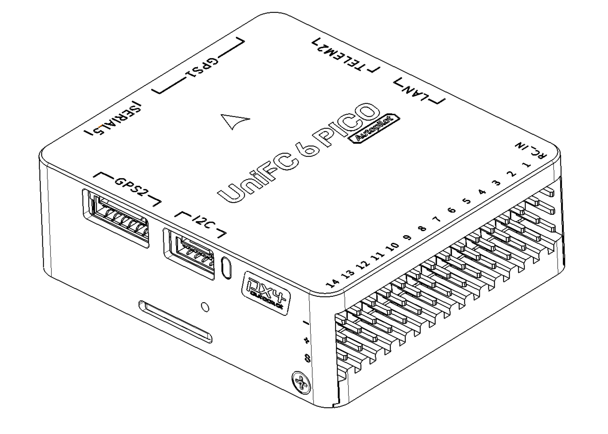
The SIYI UniFC 6 PICO is a flight controller designed by SIYI Technology. It features high-performance sensors, dual CAN bus, Ethernet connectivity, and extensive I/O options.
INFO
This flight controller is manufacturer supported.
Key Features
- MCU: STM32H743II (32 Bit Arm® Cortex®-M7, 480 MHz, 2MB Flash, 1MB RAM)
- IMU (Dual): TDK InvenSense ICM-45686 (primary, SPI4) + Bosch BMI088 accel/gyro (secondary, SPI1)
- Barometer (Dual): InvenSense ICP201XX (internal at address 0x63, external at address 0x64)
- Magnetometer: iSentek IST8310
- Interfaces:
- 6x UARTs (including GPS, telemetry, and RC ports)
- 2x CAN (DroneCAN / UAVCAN)
- 4x I²C (2 external, 2 internal)
- 1x dedicated RC Input (SBUS / DSM / SUMD)
- 14x PWM outputs (DShot-capable)
- SDMMC1 4-bit Micro-SD slot (high-speed logging)
- Ethernet (RMII, LAN8742A PHY)
- USB
- Onboard safety button
- Power:
- Single analog battery voltage/current channel (BAT1)
- Voltage sensing up to 14S LiPo by default
- On-board BECs for peripheral power (consult manufacturer for exact rail specifications)
Where to Buy
Order from SIYI.
Physical / Mechanical
- Weight: 37.9g
- Dimensions: 49.0 x 42.6 x 16.2mm
- Operating temperature: -20 ~ 85°C
Specifications
Processors & Sensors
- FMU Processor: STM32H743II
- 32 Bit Arm® Cortex®-M7, 480 MHz
- 2MB Flash, 1MB RAM
- On-board Sensors:
- Accel/Gyro 1: TDK InvenSense ICM-45686 (SPI4)
- Accel/Gyro 2: Bosch BMI088 (SPI1)
- Barometer 1: InvenSense ICP201XX (I²C3, address
0x63) - Barometer 2: InvenSense ICP201XX (I²C2, address
0x64) - Compass: iSentek IST8310 (I²C3, address
0x0E)
Power Configuration
The board provides one analog battery monitoring channel:
- BAT1 - Battery voltage and current sensed on
ADC1_INP6(voltage, PF12) andADC1_INP2(current, PF11).
The channel feeds PX4's standard analog battery driver with a default 18.181 voltage divider and 36.366 A/V current ratio, supporting up to 14S LiPo batteries out of the box.
Connectors & Pinouts
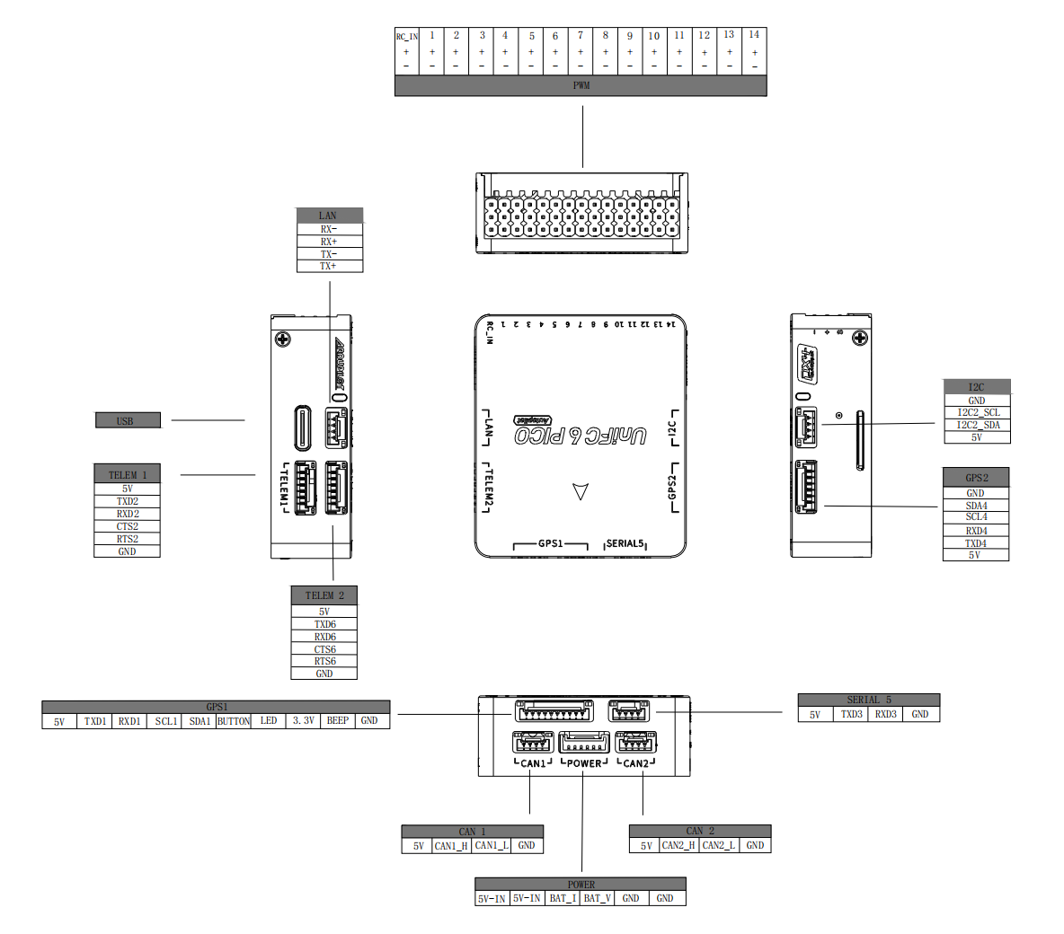
The following image shows the port connection details, including RC, UARTs, CAN, I2C, PWM, and LAN connections.
The board exposes the following connectors and solder pads:
TELEM1(6-pin) - primary MAVLink radio link (USART2)TELEM2(6-pin) - companion computer / secondary MAVLink (USART6)GPS1(10-pin JST-GH) - UBX / NMEA GPS (USART1)GPS2(6-pin) - secondary GPS (UART4)USART3(4-pin) - generic auxiliary UART breakout (USART3)RCIN(3-pin) - SBUS / DSM / SUMD receiver input (UART8)CAN1(4-pin) - FDCAN1 (DroneCAN / UAVCAN)CAN2(4-pin) - FDCAN2 (DroneCAN / UAVCAN)I2C(4-pin) - external I²CPWM- 14 PWM outputs (M1–M14)LAN(4-pin) - Ethernet (RMII data channels only)
Standard Serial Port Mapping
| Physical UART | PCB Silk Label | PX4 Slot (QGC) | Default Usage |
|---|---|---|---|
| USART1 | GPS1 | GPS 1 | GPS |
| USART2 | TELEM1 | TELEM 1 | MAVLink (Primary) |
| USART3 | USART3 | TELEM 3 | User Auxiliary |
| UART4 | GPS2 | GPS 2 | Secondary GPS |
| USART6 | TELEM2 | TELEM 2 | MAVLink (Companion) |
| UART8 | RCIN | RC | RC Input (SBUS/DSM/SUMD) |
Debug Port
The NSH console is exposed over USB CDC out of the box and is available via QGroundControl's MAVLink Console.
RC Input
RC Input is mapped to UART8 through the dedicated RCIN connector.
Only the receive line (RX8) is broken out, so the port supports:
- Single-wire SBUS (inverted)
- Spektrum DSM
- Graupner SUMD
Configure the receiver protocol with the relevant RC_*_PRT_CFG parameter from QGroundControl, pointing it at the RC slot.
PWM Output Groups
The 14 PWM outputs are organized into four timer groups. Channels in the same group must use the same output rate and DShot mode:
| Group | Timer | Channels |
|---|---|---|
| 1 | TIM1 | M1–M4 |
| 2 | TIM4 | M5–M8 |
| 3 | TIM5 | M9–M12 |
| 4 | TIM12 | M13–M14 |
Channels within the same group need to use the same output rate. If any channel in a group uses DShot then all channels in the group need to use DShot.
Ethernet
The board features an Ethernet port with RMII interface (LAN8742A PHY). Only the four RMII data channels are broken out to external pins: RMII_RXD0, RMII_RXD1, RMII_TXD0, RMII_TXD1. Other RMII signals (REF_CLK, CRS_DV, MDC, MDIO) are connected internally to the onboard PHY chip. MAVLink is pre-configured on Ethernet interface (MAV_2_CONFIG set to 1000).
Building / Loading Firmware
TIP
Most users will not need to build this firmware (from PX4 v2.0). It is pre-built and automatically installed by QGroundControl when appropriate hardware is connected.
To build PX4 for this target from source:
make siyi_unifc-6-pico_defaultInitial firmware flashing can be done over USB via QGroundControl. The bootloader status does not follow the standard generic PX4 LED indications (Green = Bootloader / Error, Blue = Active / Activity, Red = Powered).