
ZenFC H743
PX4 main (v2.0)WARNING
PX4 does not manufacture this (or any) autopilot. Contact the manufacturer for hardware support or compliance issues.
The ZenFC H743 is a flight controller designed by Zenithra Tech. It is built around the STM32H743 processor with dual Bosch BMI088 IMUs for sensor redundancy, an onboard barometer, and an integrated OSD.
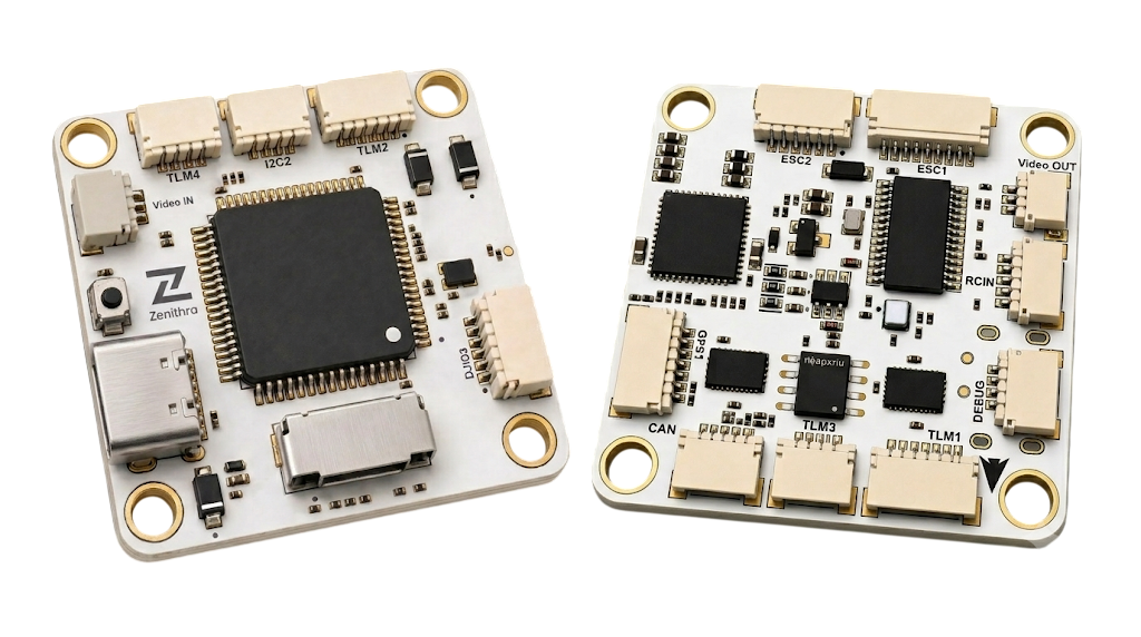
INFO
This flight controller is manufacturer supported.
Key Features
- MCU:
- STM32H743VIT6 (32-bit Arm® Cortex®-M7, 480 MHz)
- IMU:
- 2x Bosch BMI088 (accel + gyro, independent SPI buses for redundancy)
- Barometer:
- Bosch BMP388
- OSD:
- Onboard AT7456E OSD chip
- Interfaces:
- 7x UARTs
- 1x CAN
- 2x external I2C (I2C1 with GPS connector and dedicated I2C2 connector)
- 8x PWM outputs (Dshot supported)
- microSD card slot
- 1x USB Type-C
- Power:
- 2x ADC (V_BAT & current sense)
- Battery Input range - 2S-6S
- BEC Outputs
- 9V 3A cont.
- 5V 3A cont.
Dimensions
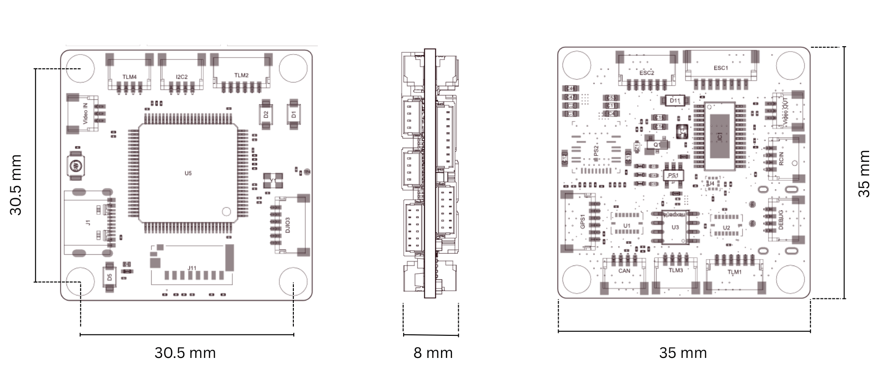
- Mounting: 30.5 mm x 30.5 mm /Φ4mm hole
- Dimensions: 35mm x 35mm x 8mm
- Weight: 9g
Where to Buy
Order from Zenithra Tech.
Flight Controller Layout
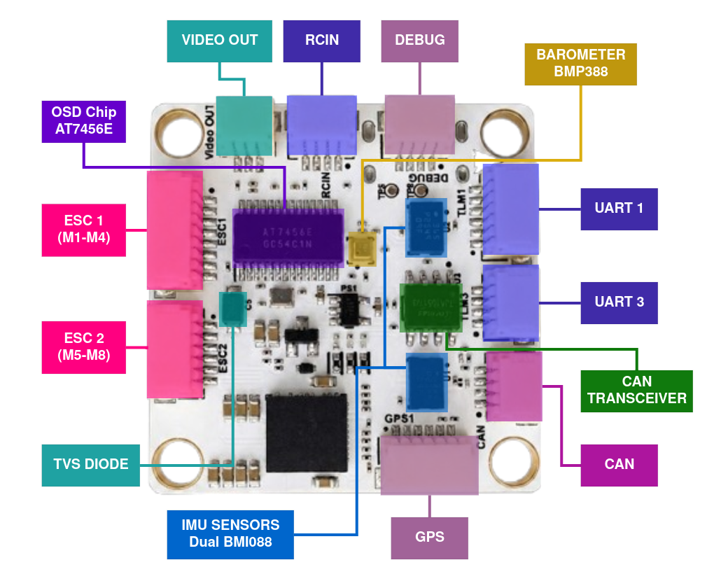
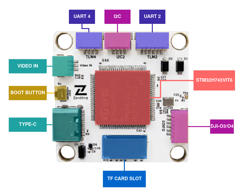
Serial Port Mapping
| UART | Device | PX4 Port |
|---|---|---|
| USART1 | /dev/ttyS0 | GPS1 |
| USART2 | /dev/ttyS1 | TEL3 |
| USART3 | /dev/ttyS2 | TEL4 |
| UART5 | /dev/ttyS3 | TEL1 |
| USART6 | /dev/ttyS4 | RC |
| UART7 | /dev/ttyS5 | TEL2 |
| UART8 | /dev/ttyS6 | UART6 |
Connectors & Pinout
Board uses JST SH connectors for all interfaces.
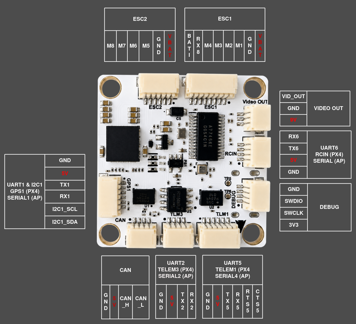
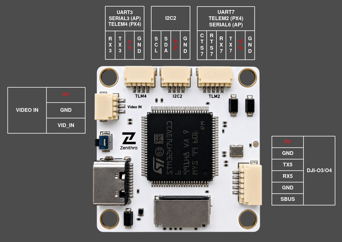
Note - SBus pin on DJI O3/O4 port is internally connected to RX6 (RCIN).
PWM Outputs
The 8 outputs are in 3 groups:
- Outputs 1-4 in group1
- Outputs 5-6 in group2
- Outputs 7-8 in group3
Note:
- All outputs support PWM and DShot protocol. Outputs 1-6 and 8 support "bidirectional DShot" (or "BDShot") telemetry.
- Outputs 1-4 default to DShot300 (PWM_MAIN_TIM0 =
-4); outputs 5-6 and 7-8 default to PWM at 400 Hz. - Each group's protocol can be changed independently using the corresponding
PWM_MAIN_TIMxparameter, including to Bidirectional DShot (BDShot) for ESC telemetry.
Debug Port
This board does not configure a dedicated UART as a system console. Use the MAVLink Shell over USB for console/NSH access using QGroundControl.
SWD
The board features a 4-pin SWD Debug interface (3V3 / SWCLK / SWDIO / GND) for hardware debugging.
Radio Control
A Radio Control (RC) system is required if you want to manually control your vehicle (PX4 does not require a radio system for autonomous flight modes). See Radio Control modules for the list of supported protocols.
RC input is mapped to USART6 (/dev/ttyS4, RC port). The port supports both single-wire inverted SBUS and full-duplex protocols with telemetry return (such as CRSF), and the receiver protocol is auto-detected by default (RC_INPUT_PROTO = -1).
PX4 Configuration
In addition to the basic configuration, the following parameter is important:
| Parameter | Setting |
|---|---|
| SYS_HAS_MAG | Disabled by default since the board has no internal magnetometer. Enable it if you attach an external mag. |
Building Firmware
To build PX4 for this target:
make zenfc_h743_defaultInstalling PX4 Firmware
The firmware can be installed in any of the normal ways:
Build and upload the source:
shmake zenfc_h743_default uploadLoad the firmware using QGroundControl. You can use either pre-built firmware or your own custom firmware.
The board uses the standard PX4 bootloader, so it follows the same generic LED indications as most other boards (Red = Bootloader/Error, Blue = Active/Activity, Green = Powered).