
Agam Autopilot v6X-RT
main (PX4 v2.0)WARNING
PX4 does not manufacture this (or any) autopilot. Contact the manufacturer for hardware support or compliance issues.
The Agam Autopilot v6X-RT flight controller is Agam Robotics' implementation of the NXP-led FMUv6X-RT reference design.
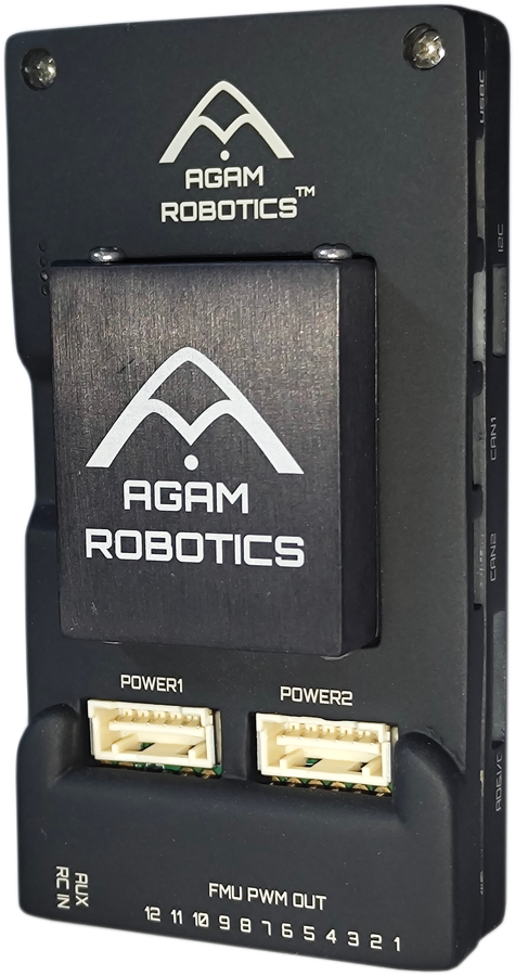
INFO
This flight controller is manufacturer supported.
Introduction
Agam Autopilot v6X-RT uses the NXP i.MX RT1176 MCU, consisting of an Arm® Cortex®-M7 core at 1GHz and an Arm® Cortex®-M4 core at 400MHz, with 2MB SRAM and 64MB Octal SPI flash. The increased processing power lets firmware developers run more complex algorithms without being constrained by the flight controller's compute budget.
The board uses sensors from InvenSense® and Bosch®, and ships in two sensor-set variants (see Processors & Sensors). Redundant IMU and barometer sensors sit on separate buses, and 2 of the 3 IMUs are mounted on a shock-isolated, heated sensor board, separate from the FMU board itself, to improve accuracy in flight and across a wide temperature range.
An integrated Ethernet interface (100BASE-T1, 2-wire) provides high-speed, low-latency connectivity to companion computers (for example a Raspberry Pi or NVIDIA Jetson), cameras, or data-transmission systems.
Key Design Points
- High-performance NXP i.MX RT1176 dual-core MCU
- NXP EdgeLock SE051 hardware secure element, field-updatable, certified to CC EAL 6+
- Triple redundant IMU (2 sensors on a shock-mounted, heated sensor board, 1 on the FMU board itself) and dual redundant barometer, each on a separate bus
- Independent power control and separate buses for each sensor domain
- 100BASE-T1 (2-wire) automotive Ethernet for high-speed companion computer integration
- 256Kbit FRAM
TIP
This board ships with SENS_IMU_MODE and EKF2_MULTI_IMU set so that only the FMU-board IMU is used by default. To take advantage of the triple-redundant IMU set SENS_IMU_MODE to Disabled (0), reboot, set EKF2_MULTI_IMU to 3, and reboot again. See Agam's IMU triple redundancy notes for more information.
Processors & Sensors
- FMU Processor: NXP i.MX RT1176 (MIMXRT1176DVMAA)
- Arm® Cortex®-M7 core @ 1GHz
- Arm® Cortex®-M4 core @ 400MHz (secondary core)
- 2MB SRAM
- 64MB external Octal SPI flash
- On-board sensors — Agam Autopilot v6X-RT ships in two sensor-set variants (Sensor Set 1 and Sensor Set 3, per Pixhawk Standards):
Electrical data
- Voltage Ratings:
- Max input voltage: 6V
- USB Power Input: 4.75~5.25V
- Servo Rail Input: 0~36V
- Current Ratings:
TELEM1output current limiter: 1.5A- All other port combined output current limiter: 1.5A
Mechanical data
- Dimensions
- Flight controller module: 39 x 32 x 16 mm
- Baseboard: 95 x 50 x 19 mm
- Weight: 90 g
- Operating temperature: -40°C to 85°C
Interfaces
- 12 PWM/DShot outputs (8 DShot-capable, 4 PWM-only)
- 1x RC input, SBUS/PPM
- 1x dedicated DSM/Spektrum RC input
- 3x TELEM ports (
TELEM1,TELEM2,TELEM3), full flow control - 2x GPS ports (
GPS1full GPS plus safety switch and buzzer,GPS2basic) - 4x I2C
- 3x CAN-FD
- 1x SPI bus, 2 chip-select lines, 2 data-ready lines, 1 sync line, 1 reset line
- 1x NFC antenna port (connected to the SE051 secure element)
- 100BASE-T1 Ethernet (single 2-wire port)
- USB 2.0
- microSD card slot
- Dual redundant power input (5V via Molex connectors)
Where To Buy
Order from the Agam Robotics store.
Assembly/Setup
Agam Autopilot v6X-RT is a Pixhawk-standard v6X-RT board, electrically and mechanically identical to the NXP reference design, differing from it only in enclosure. Wiring is similar to the Holybro Pixhawk 6X and other boards that follow the Pixhawk Connector Standard.
For wiring and assembly, follow the Pixhawk 6X Wiring Quick Start, which applies to this board other than the enclosure.
Connections
The connectors follow the Pixhawk Connector Standard, which defines the pinout of each port type. For the physical layout of the ports on the board see the Agam Autopilot v6X-RT baseboard ports documentation.
Pinouts
Agam Autopilot v6X-RT's pinout is the same as other v6X-RT-family boards:
- DS-012 Pixhawk Autopilot v6X Standard
- DS-010 Pixhawk Autopilot Bus Standard
- DS-009 Pixhawk Connector Standard
- Agam Autopilot v6X-RT Baseboard Port pinouts (agamrobotics.gitbook.io)
Notes:
- The camera capture pin (
PI0) is pin 2 on the AD&IO port, markedFMU_CAP.
Serial Port Mapping
| UART | Device | Port |
|---|---|---|
| LPUART1 | /dev/ttyS0 | Console |
| LPUART3 | /dev/ttyS1 | GPS |
| LPUART4 | /dev/ttyS2 | TELEM1 |
| LPUART5 | /dev/ttyS3 | GPS2 |
| LPUART6 | /dev/ttyS4 | PX4IO |
| LPUART8 | /dev/ttyS5 | TELEM2 |
| LPUART10 | /dev/ttyS6 | TELEM3 |
| LPUART11 | /dev/ttyS7 | EXT2 |
Radio Control
A remote control (RC) radio system is required if you want to manually control your vehicle (PX4 does not require a radio system for autonomous flight modes). You will need to select a compatible transmitter/receiver and then bind them so that they communicate (read the instructions that come with your specific transmitter/receiver).
The ports and supported protocols are:
RC IN(FMU): SBUS/PPMDSM RC(FMU): Spektrum/DSM
For PPM and S.Bus receivers, a single signal wire carries all channels. If your receiver outputs individual PWM signals (one wire per channel) it must be connected via a PPM encoder.
Voltage Ratings
Agam Autopilot v6X-RT can be triple-redundant on the power supply if three power sources are supplied. The three power rails are: POWER1, POWER2 and USB. The POWER1 & POWER2 ports use a 6-circuit 2.00mm Pitch CLIK-Mate Wire-to-Board PCB Receptacle.
Normal Operation Maximum Ratings
Under these conditions all power sources will be used in this order to power the system:
- POWER1 and POWER2 inputs (4.9V to 5.5V)
- USB input (4.75V to 5.25V)
Absolute Maximum Ratings
Under these conditions the system will not draw any power (will not be operational), but will remain intact.
- POWER1 and POWER2 inputs (operational range 4.1V to 5.7V, 0V to 10V undamaged)
- USB input (operational range 4.1V to 5.7V, 0V to 6V undamaged)
- Servo input: VDD_SERVO pin of FMU PWM OUT (0V to 42V undamaged)
Digital I2C battery monitoring is enabled by default. Analog/ADC battery monitoring is also supported.
Building Firmware
TIP
Most users will not need to build this firmware from PX4 v2.0. It will be pre-built and automatically installed by QGroundControl when appropriate hardware is connected.
To build PX4 for this target:
make agam_fmu-v6xrt_defaultDebug Port
The PX4 System Console and SWD interface run on the FMU Debug port.
The pinout and connector comply with the Pixhawk Debug Full interface defined in the Pixhawk Connector Standard (JST SH 1mm pitch, 10-pin connector). Pin 6 is SPI6_MOSI_EXTERNAL1, which is the pad's JTAG_TDO function and carries SWO when the debug port is in serial-wire mode.
| Pin | Signal | Volt |
|---|---|---|
| 1 (red) | FMU_VDD_3V3 | +3.3V |
| 2 (black) | FMU_USART_TX | +3.3V |
| 3 (black) | FMU_USART_RX | +3.3V |
| 4 (black) | FMU_SWD_IO | +3.3V |
| 5 (black) | FMU_SWD_CK | +3.3V |
| 6 (black) | SWO | +3.3V |
| 7 (black) | NFC GPIO | +3.3V |
| 8 (black) | PH11 | +3.3V |
| 9 (black) | FMU_nRST | +3.3V |
| 10 (black) | GND | GND |
For information about using this port see:
Peripherals
- Agam GNSS01 CAN
- Agam GNSS02 CAN RTK
- Agam GNSS Base RTK
- Agam FloRange Sensor
- Rangefinders/Distance sensors
- Telemetry Radio Modules
Further info
- Update Pixhawk 6X-RT Bootloader
- Agam Autopilot v6X-RT Documentation (Agam Robotics Docs)
- Agam Autopilot v6X-RT setup video playlist (YouTube, Agam Robotics)
- Pixhawk 6X Wiring QuickStart
- Agam Digital Power Module (DPM01)
- Agam Analog Power Module (APM)
- Announcing the Pixhawk FMUv6X-RT (Dronecode Foundation)
- Pixhawk FMUv6X-RT open standard
- Pixhawk Autopilot Bus Standard
- Pixhawk Connector Standard