
NXP MR-NavQ95
main (PX4 v2.0)WARNING
PX4 does not manufacture this (or any) autopilot. Contact the manufacturer for hardware support or compliance issues.
The MR-NavQ95 is a vehicle computer reference design from NXP Mobile Robotics, built around the NXP i.MX 95. Linux runs on the Cortex-A55 cores, and PX4 runs on the Cortex-M7 real-time core, started by MCUboot from the on-board octal NOR flash. The two sides talk over RPMsg: PX4 keeps its parameters, dataman and logs on a filesystem served by Linux, and exposes its shell and two MAVLink links as virtual ttys on the Linux side. The main board carries the i.MX 95 and the ICM-45686, BMM350 and BMP581 sensors. The NAVQ95-IO expansion board (the "IO board") carries the BMI088, the USB console, and the CAN, PWM, GPS, TELEM and I2C connectors.
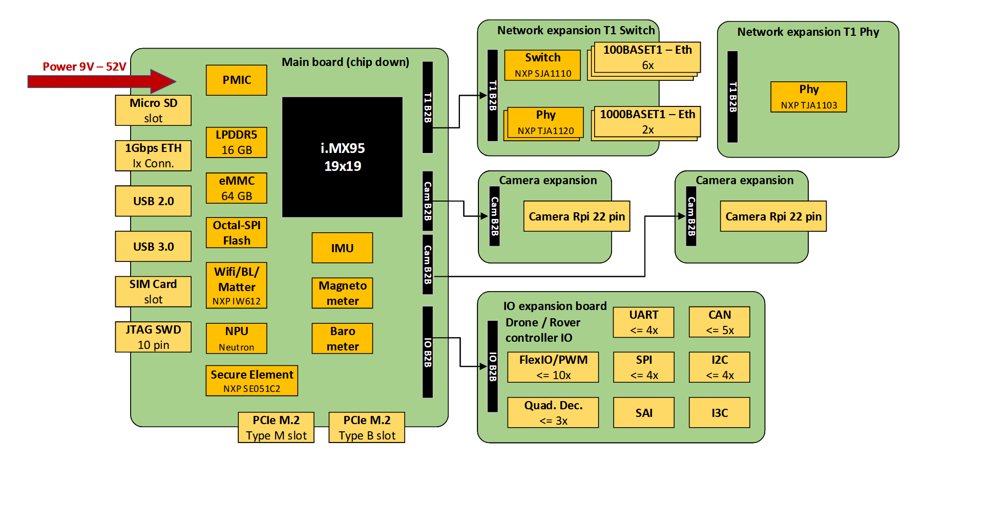
Because the i.MX 95 is an applications processor, the Linux side is a full companion computer rather than just a storage and telemetry bridge. It brings the parts of a mobile robotics stack that do not belong on a flight controller:
- Up to 6x Arm Cortex-A55 application cores running Linux, next to the Cortex-M7 real-time core used by PX4 and a Cortex-M33 for boot and system control
- eIQ Neutron NPU for on-device machine learning, for example object detection, segmentation or visual navigation, without an external accelerator
- Image Signal Processor with multiple MIPI-CSI inputs, so several cameras (for example a stereo pair plus an RGB camera) can be attached at once
- Arm Mali GPU and hardware H.264/H.265 encode and decode for video streaming and recording
- Audio subsystem (SAI, microphone array support) for voice interaction and acoustic sensing
- Networking: a gigabit RJ45 port on the main board straight off the SoC, plus a second SoC Ethernet port brought out as a SerDes lane (SGMII, USXGMII or XFI) on the Hirose board-to-board header
J17 B2B_ETHfor one networking expansion board:- NAVQ95-T1SW: an NXP SJA1110 TSN switch on the SGMII link, with two 1000BASE-T1 and six 100BASE-T1 automotive Ethernet ports for multi-drop vehicle networks
- X-MR-NAVQ95E-T1P: a single NXP TJA1103 100BASE-T1 PHY
- An SFP+ cage board (to be released): the lane runs as XFI into the SFP+ cage, so the 10 Gbit link can be fibre with an optical module or copper with a direct-attach (DAC) cable
- PCIe, USB and an on-board Wi-Fi/Bluetooth module for links to the ground station and to other vehicles
INFO
Only the Cortex-M7 side is PX4. All of the above is available to the application running on Linux, which talks to PX4 over the RPMsg MAVLink link described below.
INFO
This flight controller is manufacturer supported.
Specifications
Processor
- Main FMU processor: NXP i.MX 95. PX4 runs on its Arm® Cortex®-M7 core (800 MHz). The Cortex®-A55 cores run Linux and the Cortex®-M33 core runs the NXP System Manager.
- Code store: on-board octal NOR flash. MCUboot starts PX4 from slot0 (7 MB), the primary image slot in the NOR flash (see Flash Layout). The
ddrbuild runs from SDRAM and is loaded by Linux.
Sensors
- IMU: TDK InvenSense ICM-45686 (SPI1, on the main board), Bosch BMI088 (SPI8, on the IO board)
- Barometer: Bosch BMP581 (I2C1, on the main board)
- Magnetometer: Bosch BMM350 (I2C1, on the main board)
Interfaces
- PWM outputs: 8 FMU outputs (7 when
GPIO_IO23is configured as the buzzer or left unused), all DShot capable, including bidirectional DShot 300 and 600 - Serial ports: 3 (
GPS1,TELEM1with flow control, RC on the main boardJ2 CONSOLE), plus RPMsg virtual ports to Linux (shell, two MAVLink links) - I2C buses: 2 (I2C1 internal, I2C6 external)
- SPI buses: 2, both internal
- CAN buses: 2 CAN FD buses for PX4, DroneCAN capable (IO board
J4 CAN2andJ3 CAN3). A third (IO boardJ5 CAN1) belongs to Linux. - Ethernet: none on the PX4 side
- USB: none on the PX4 side (the USB ports belong to Linux)
- RC input: Yes
- Parameter storage: a file on the RPMsg filesystem served by Linux (
/fs/rpmsg/params) - SD card: none on the PX4 side
Electrical Data
- Input voltage: 9 V to 52 V (3S to 12S battery), 60 V absolute maximum
- Input power: 60 W between 9 V and 20 V, 125 W between 20 V and 52 V
- Power monitoring: 1 analog input, voltage only (
ADC_IN0measures VIN/64, hence theBAT1_V_DIVdefault of 64.4)
Mechanical Data
- Dimensions: main board 137 x 112 mm, IO board 120 x 79 mm (PCB outline; height and weight are not specified)
- Memory for PX4: 256 KB ITCM, 256 KB DTCM and 256 KB OCRAM on the Cortex-M7, and a 7 MB flash slot
- Operating temperature: the SoC (
MIMX9596AVZXNMC, automotive grade) is rated -40 °C to 105 °C ambient (125 °C junction) in the i.MX 95 data sheet. The board-level operating temperature is not specified.
Where to Buy
The board is not yet released. Its release will be announced in the MR-NAVQ95 repository.
Pinouts
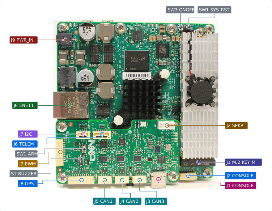
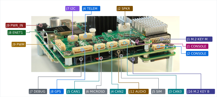
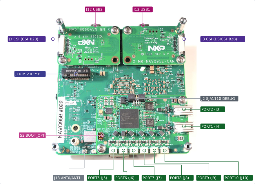
Hardware details, schematics and the pinout of every connector are in the MR-NAVQ95 repository. The connector index has a drawing and a pin table for each connector.
The TELEM, GPS, I2C and CAN connectors follow the Dronecode DS-009 connector standard. The main board J2 CONSOLE header has its own pin order: pins 4 and 5 carry the RC UART (see Radio Control). The PWM header (IO board J9 PWM) has its own pin order.
Power
The board is powered through the main board J9 PWR_IN connector (Molex Micro-Fit 3.0, 2-pin) from 9 V to 52 V.
Battery monitoring is analog and voltage only, with BAT1_V_DIV set to 64.4 by default. For battery and power module configuration see Battery and Power Module Setup.
The PWM output rail is not powered by the board's power input (main board J9 PWR_IN). The output rail must be separately powered if it needs to power servos or other hardware. The rail (IO board J9 PWM pin 1, VDD_CON_PWM) can only be linked to the board 5 V by fitting R60 (0 ohm), which is not fitted by default. Do not put more than 5 V on the servo rail while R60 is fitted.
WARNING
Never feed power into the 5 V pins of the JST-GH connectors; they are outputs.
Voltage Ratings
Normal Operation Maximum Ratings
PWR_IN(main boardJ9): 9 V to 52 V
Absolute Maximum Ratings
PWR_IN(main boardJ9): 60 V- Servo rail (
VDD_CON_PWM, IO boardJ9pin 1): 12 V with R60 not fitted (the rail is only sensed, throughADC_IN6), 5 V with R60 fitted
PWM Outputs
The 8 outputs are on the IO board J9 PWM connector (3.3 V logic), in 4 groups:
- Outputs 1-3 in group 1 (TPM3)
- Outputs 4-5 in group 2 (TPM4)
- Outputs 6-7 in group 3 (TPM5)
- Output 8 in group 4 (TPM6)
Output 8 (GPIO_IO23, IO board J9 pin 9) can be turned into the GPS buzzer output under GPIO_IO23 in the board configuration, which enables the tone alarm driver. The buzzer only sounds with DIP switch S1 closed. To use output 8 as a PWM/DShot output, set S1 open (off); with S1 closed the output also drives the buzzer.
All outputs support PWM, DShot and bidirectional DShot (300 and 600). Outputs in a group share the same protocol and rate, which are set per group with the corresponding PWM_MAIN_TIMx parameter.
Serial Port Mapping
| UART | Device | Port | Flow Control |
|---|---|---|---|
| LPUART2 | /dev/ttyS1 | RC (or NSH console over the IO board USB serial) | No |
| LPUART5 | /dev/ttyS4 | GPS1 | No |
| LPUART7 | /dev/ttyS6 | TELEM1 | Yes |
LPUART2 is the M7 console port: it reaches the CP2105 USB serial bridge on the IO board (J1 CONSOLE, ttyUSB1 on a Linux host) and the main board J2 CONSOLE header (pins 4 and 5). It is the RC input by default, and the board configuration (LPUART2 under MR-NavQ95 board options in make nxp_mr-navq95_default boardconfig) can run an NSH console on it instead. If you select the console, also clear CONFIG_BOARD_SERIAL_RC in the same board configuration; the build fails otherwise. The schematic and connector drawings name the LPUARTn ports UARTn (UART2 is LPUART2, and so on). UART2 TX is also the BT_MODE1 boot strap, so leave that line idle while the board resets.
WARNING
With LPUART2 used for RC, do not connect a PC to the second CP2105 port (ttyUSB1) of the IO board J1 CONSOLE connector. Its transmitter shares the line with the RC receiver and interferes with the RC UART.
Assembly
Radio Control
A remote control (RC) radio system is required if you want to manually control your vehicle (PX4 does not require a radio system for autonomous flight modes).
You will need to select a compatible transmitter/receiver and then bind them so that they communicate (read the instructions that come with your specific transmitter/receiver).
The receiver (for example CRSF, ELRS or SBUS) connects to the main board J2 CONSOLE header:
| Pin | Signal | Connection |
|---|---|---|
| 1 | 5 V | Receiver power |
| 2 | UART1 TX | Linux console |
| 3 | UART1 RX | Linux console |
| 4 | UART2 RX | Receiver TX |
| 5 | UART2 TX | Receiver RX, only needed for bidirectional protocols such as CRSF telemetry |
| 6 | GND | Receiver ground |
CRSF receivers are enabled by default (RC_CRSF_PRT_CFG is set to the RC port). You can enable other protocols by mapping them to the port using their associated parameters, such as RC_DSM_PRT_CFG, RC_GHST_PRT_CFG, RC_SBUS_PRT_CFG. Note that only one protocol can be active on a port, so you will have to first disable RC_CRSF_PRT_CFG.
There is no PPM input. PX4 can't bind DSM receivers on this board; use the receiver's or transmitter's own bind procedure.
GPS & Compass
PX4 supports GPS modules connected to the GPS port described below. The module should be mounted on the frame as far away from other electronics as possible, with the direction marker pointing towards the front of the vehicle.
The GPS port is the IO board J8 GPS connector, a standard DS-009 GPS and compass connector:
- UART5 (
GPS1,/dev/ttyS4) for the GPS - I2C6 for an external compass (also on the IO board
J7 I2Cconnector) - Safety switch line (not supported by PX4 on this board yet)
- Safety LED (on the IO board I/O expander, not driven yet)
- Buzzer (needs DIP switch
S1closed and the GPIO_IO23 buzzer option, see PWM Outputs)
The main board has an on-board Bosch BMM350 magnetometer. An external compass on the IO board J8 GPS or J7 I2C connector (I2C6) is detected automatically at boot.
Telemetry Radios (Optional)
Telemetry radios may be used to communicate and control a vehicle in flight from a ground station (for example, you can direct the UAV to a particular position, or upload a new mission).
The vehicle-based radio should be connected to the IO board J6 TELEM connector (DS-009), which is UART7 (TELEM1) with flow control. A radio on TELEM1 needs no further configuration. Without a radio, MAVLink runs over RPMsg to Linux (see MAVLink and QGroundControl).
CAN
PX4 uses two of the three CAN FD buses:
can0is FlexCAN2 on the IO boardJ4 CAN2connectorcan1is FlexCAN3 on the IO boardJ3 CAN3connector
The IO board J5 CAN1 connector belongs to Linux. Each port has 120 ohm split termination, so each port is a bus end.
DroneCAN is off by default. The board brings up can0 and can1 only when UAVCAN_ENABLE is above 0.
Linux Side
The Linux side must run the NavQ95 BSP built from imx-manifest-navq95. It provides the RPMsg links PX4 depends on:
| Linux device | PX4 side | Purpose |
|---|---|---|
/dev/ttynsh | NSH console | PX4 shell (the system console) |
/dev/ttyproxy | mavlink in onboard mode | MAVLink at 921600 baud for the companion computer |
/dev/ttymavmin | mavlink in minimal mode | Second MAVLink link at 115200 baud (flags in rc.board_mavlink) |
/dev/ttyros | uxrce_dds_client (off by default) | uXRCE-DDS link for ROS 2, registered as serial port TELEM 2 (see ROS 2) |
PX4 has no local storage. /fs/rpmsg on the PX4 side is an RPMsg filesystem (rpmsgfs) served by Linux, and it holds the parameters, dataman and the flight logs.
WARNING
This means PX4 depends on Linux for parameter storage: the parameters are only readable and writable once the Linux side has booted and the rpmsgfs server is running. Keeping the parameters on the on-board octal NOR flash instead, so the M7 is self-contained, is still work in progress (see Current Status).
MAVLink and QGroundControl
There is no telemetry radio in the path by default: the MAVLink link leaves the board over the network.
The onboard-mode mavlink instance on PX4 shows up on Linux as /dev/ttyproxy. To on-board software it looks like an autopilot on a serial port: MAVSDK, MAVROS or any other MAVLink application from the companion computer guide can open it directly. The imx-image-ros image instead runs mavlink-router as a service on that device (on imx-image-mr you have to install it yourself). It republishes the stream on the network, so several clients can use the same link at the same time:
PX4 (M7) --RPMsg--> /dev/ttyproxy --> mavlink-router --> UDP/TCP on Wi-Fi or EthernetThe shipped configuration (/etc/mavlink-router/main.conf) listens for UDP on port 10000 and does not broadcast, so the Wi-Fi is not flooded with UDP traffic that access points tend to drop. The ground station therefore has to connect to the board: in QGroundControl, add a UDP comm link with the board's IP address and port 10000 as its server. To push the stream to a fixed ground station instead, add a UdpEndpoint with Mode = Normal and the ground station's Address and Port (14550 for QGroundControl) to that file. The endpoint types and modes are described in the mavlink-router README. On-board software can attach to further endpoints of the router in parallel.
TIP
If QGroundControl does not find the vehicle, check that the RPMsg links came up on Linux (ls /dev/ttyproxy) and that mavlink-router is running (systemctl status mavlink-router) before looking at PX4.
ROS 2
The RPMsg link /dev/ttyros is registered as the TELEM 2 serial port of PX4, but nothing runs on it by default. To use ROS 2 through the uXRCE-DDS bridge:
Set UXRCE_DDS_CFG to
TELEM 2and reboot PX4. The client then starts on/dev/ttyrosat theSER_TEL2_BAUDrate (921600 by default, which only has to match the agent).Install the Micro XRCE-DDS Agent on the Linux side; the images do not ship it.
Start the agent on the same device:
shsudo MicroXRCEAgent serial --dev /dev/ttyros -b 921600
The PX4 topics then appear in ROS 2 on the board, as described in the ROS 2 User Guide.
Building Firmware
To build PX4 for this target:
make nxp_mr-navq95_defaultThe build writes two images:
build/nxp_mr-navq95_default/nxp_mr-navq95_default.bin, the plain binary.build/nxp_mr-navq95_default/nxp_mr-navq95_default.signed.bin, the plain binary wrapped with the MCUboot header and SHA256 trailer byimgtool. This is the image MCUboot boots from slot0.
The MCUboot header size, slot size and alignment are set in default.px4board (CONFIG_BOARD_MCUBOOT_IMGTOOL_ARGS) and match the on-board MCUboot, which is built with CONFIG_BOOT_SIGNATURE_TYPE_NONE. imgtool is installed by the PX4 setup scripts (Tools/setup/requirements.txt); if it is missing, the build warns and skips the signed image.
The ddr label (make nxp_mr-navq95_ddr) runs from SDRAM and is loaded by Linux instead of MCUboot, so it has no signed image.
Signing with a Key
The default image carries only a SHA256 trailer and boots on an MCUboot built with CONFIG_BOOT_SIGNATURE_TYPE_NONE. For an MCUboot that verifies signatures, generate a key, pass it in the environment when configuring the build, and bake the matching public key into MCUboot:
python3 -m imgtool.main keygen -k navq95-signing.pem -t ecdsa-p256
BOARD_MCUBOOT_KEY=/path/to/navq95-signing.pem make nxp_mr-navq95_default
python3 -m imgtool.main getpub -k navq95-signing.pem   # for the MCUboot build
The key type must match the MCUboot signature type (ecdsa-p256, rsa-2048, rsa-3072 or ed25519). The key is read when CMake configures, so changing it needs a fresh build directory. Keep the private key out of the repository.
Installing PX4 Firmware
INFO
MCUboot boots PX4 from slot0 reliably, but the update path is still a developer flow over SWD. A convenient field update (image upload through Linux into slot1 and an MCUboot swap) is not in place yet; see Current Status.
Flash Layout
The octal NOR flash is mapped at 0x28000000 in the Cortex-M7 address space. MCUboot, built from Zephyr in the NavQ95 BSP (board mr_navq95b), defines the partitions, and the PX4 linker script and imgtool arguments match slot0:
| Address | Size | Partition | Use |
|---|---|---|---|
0x28000000 | 128 KB | mcuboot | MCUboot bootloader |
0x28020000 | 7 MB | slot0 (image-0) | Primary slot, PX4 runs from here (execute in place) |
0x28720000 | 7 MB | slot1 (image-1) | Secondary slot for an uploaded update, swapped into slot0 by MCUboot |
0x28E20000 | 1920 KB | storage | Reserved for the planned on-flash parameter storage (see Current Status) |
The rest of the flash is unused.
The firmware is flashed into MCUboot slot0 over SWD with pyOCD. Mainline pyOCD has no i.MX 95 support; use the NXP-Robotics fork, branch pr-imx95, which adds the mimx95_* targets and the NOR flash algorithm:
git clone https://github.com/NXP-Robotics/pyOCD -b pr-imx95
cd pyOCD
python3 -m pip install .
Set the boot switches and power the board as described in the NavQ95 manifest README, then:
pyocd flash -e sector -a 0x28020000 -t mimx95_cm7_mx25um -f 20M \
  -O vtor=0x28020800 build/nxp_mr-navq95_default/nxp_mr-navq95_default.signed.bin
pyocd reset -t mimx95_cm33 -f 20M
-a 0x28020000is slot0 (see Flash Layout). pyOCD would otherwise default to the start of the flash region (0x28000000), which is MCUboot's own partition.-O vtor=0x28020800is slot0 plus the 0x800-byte header, i.e. the application vector table. pyOCD's CM7 reset on this SoC is a core-only restart: it writes VTOR, loads MSP/PC from that table and resumes, so the application starts directly without going through MCUboot.- The debugger-initiated reset after flashing (
pyocd reset -t mimx95_cm33) does not chain-load slot0: MCUboot stays in its serial-recovery loop ("Unable to find bootable image") even though the image in slot0 is valid. Power-cycle the board to boot PX4 from slot0.
Debug Port
The PX4 system console is /dev/ttynsh on the Linux side. An NSH shell that does not need Linux can run on LPUART2 (IO board J1 CONSOLE or main board J2 CONSOLE) instead of the RC input; see Serial Port Mapping.
The SWD interface is on the main board J7 DEBUG connector, a standard Arm Cortex 10-pin header (2x5, 1.27 mm), for an external debug probe (J-Link, CMSIS-DAP or any probe pyOCD supports; see the J7 card in the MR-NAVQ95 repository). It is not a Pixhawk Debug Full or Debug Mini connector. VTref is 1.8 V, so the probe must support 1.8 V targets. nRESET is connected through a diode, so the probe can only pull it low. With pyOCD, the M7 core is reached with pyocd gdb -t mimx95_cm7_mx25um.
Current Status
The MR-NavQ95 is a reference design under active development, and the PX4 port is not feature complete. Known gaps at the time of writing:
- Firmware update: MCUboot in the NOR flash boots the signed PX4 image from slot0, but the only supported way to get an image in there is SWD with pyOCD. There is no Linux-side updater or serial-recovery flow yet, so updating PX4 still needs a debug probe and the boot switches set for flashing. MCUboot itself is still work in progress.
- Parameter and log storage: Parameters, dataman and logs live on the RPMsg filesystem served by Linux. Moving the parameter storage to the on-board octal NOR flash, so that PX4 can boot and arm independently of the Linux side, is in progress.
- Virtual Ethernet for PX4: All networking is handled by Linux today; PX4 reaches the network only indirectly through the RPMsg MAVLink tty and mavlink-router. A VSI (virtual station interface) network driver for PX4/NuttX, which would give PX4 its own virtual Ethernet interface on the shared MAC, is in progress. With that in place, MAVLink over UDP, uXRCE-DDS, Zenoh-pico and native ROS 2 publishing can run directly from the M7 instead of being proxied by Linux.
- Reboot: The
rebootcommand,MAV_CMD_PREFLIGHT_REBOOT_SHUTDOWNand the reboot that QGroundControl requests after calibration or airframe selection do not restart the M7 yet; power-cycle the board instead. An M7 reset through the i.MX 95 System Manager is planned. - PWM timing and input capture: Output group 1 (TPM3) runs from a 133 MHz clock root. OneShot is not supported yet on any output, and neither is bidirectional DShot 150. The PWM timing code is being reworked, and PWM input capture is not available.
- Defaults may change: Port assignments, PWM groups and board defaults can still change as the design and the BSP evolve; check the board files and the BSP manifest against the version you are running.