
Accton Godwit G-FH7
main (PX4 v2.0)WARNING
PX4 does not manufacture this (or any) autopilot. Contact the manufacturer for hardware support or compliance issues.
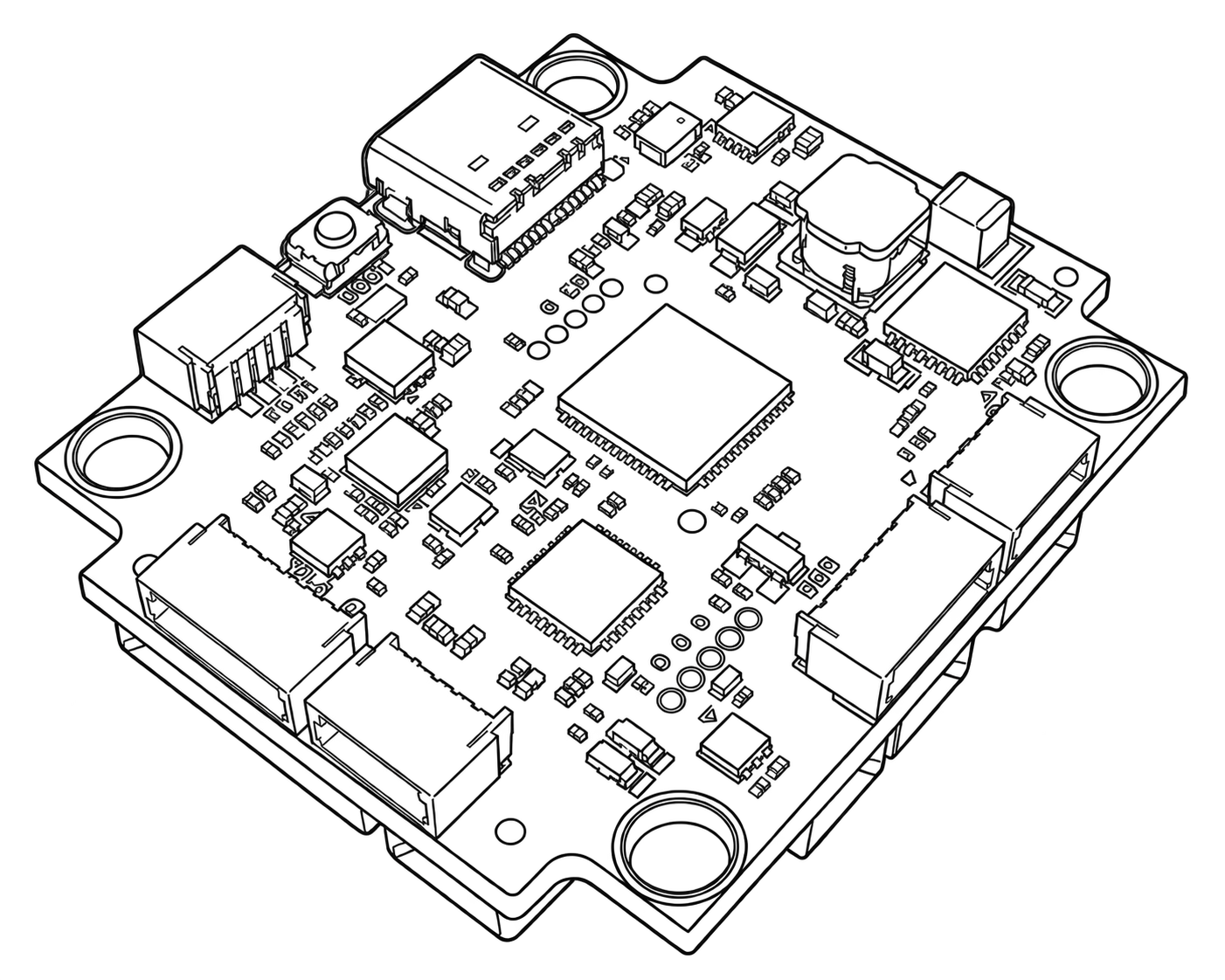
The Godwit G-FH7 is a compact flight controller from Accton, designed for fixed-wing, VTOL, and other UAV applications. It uses an STM32H753 flight-management processor, dual IMUs, an integrated barometer and compass, and solder-free connectors for flexible system integration. The board supports PX4, ArduPilot, Betaflight, and iNAV flight-control software.
INFO
This flight controller is manufacturer supported.
Specifications
Processor
- Main FMU processor: STM32H753VIH6 (Arm® Cortex®-M7 at 480MHz, 2MB flash, 1MB RAM)
Sensors
- IMU: TDK InvenSense ICM-42688-P (SPI4), STMicroelectronics LSM6DSK320X (SPI2)
- Barometer: Infineon DPS368 (I2C1)
- Magnetometer: iSentek IST8310 (I2C1)
- Heater: resistive IMU heater, off by default (see IMU Heater)
Interfaces
- PWM outputs: 8 (plus
PWM9for a NeoPixel LED strip) - Serial ports: 7:
TELEM,GPS,ELRS,SBUS,D-VTX,ESC(ESC telemetry, RX only), and theT2/R2solder pads - I2C buses: 2 (1 external, 1 internal)
- SPI buses: 3, all internal (both IMUs and the OSD)
- CAN buses: 1
- Ethernet: RMII and pulse-per-second (PPS) signals on a connector (reserved for future use; not enabled in PX4)
- USB: USB Type-C, with
BOOTbutton for DFU mode - RC input: Yes (serial, on the
SBUSandELRSconnectors) - Parameter storage: processor flash
- SD card: microSD slot
- ADC inputs: 3 (battery voltage, battery current, and analog RSSI, which PX4 doesn't read)
- OSD: analog (AT7456-compatible)
- Other: 2 LED indicators, active buzzer output, video input, and video output
Electrical Data
- Input voltage: Up to 12S LiPo
- Current draw: 110mA at 5V (static), plus about 67mA (0.33W, calculated) with the IMU heater on
- BEC output: 5V/3A and 12V/3A (12V output switchable)
- Power monitoring: 1 battery, analog voltage and current (current needs setup)
Mechanical Data
- Dimensions: 36 x 42 x 8.63mm
- Weight: 10.6g
- Mounting hole spacing: 30.5 x 30.5mm, M4
Where to Buy
Product information and availability are provided on the Accton-IoT Godwit G-FH7 product page.
Pinouts
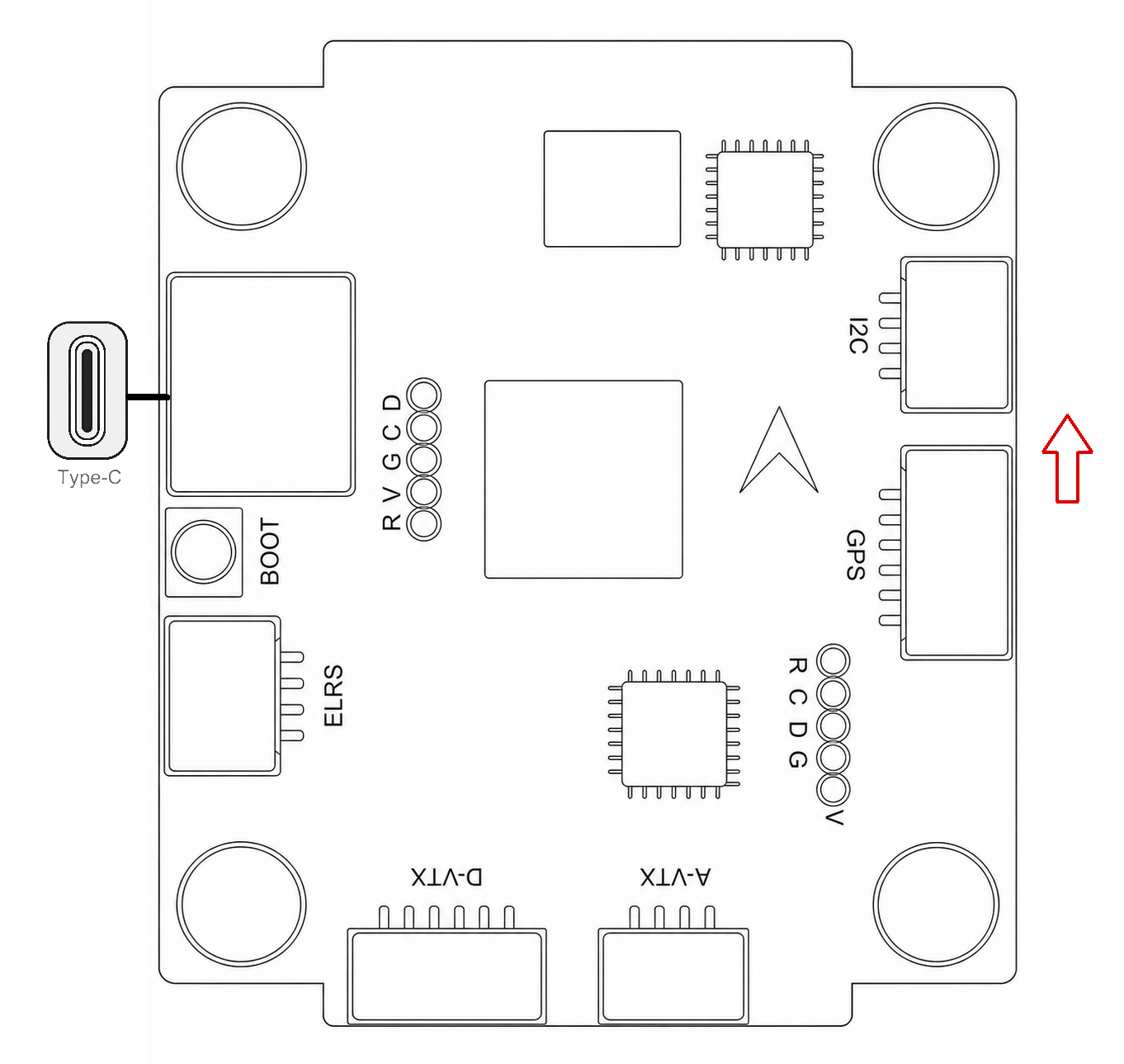
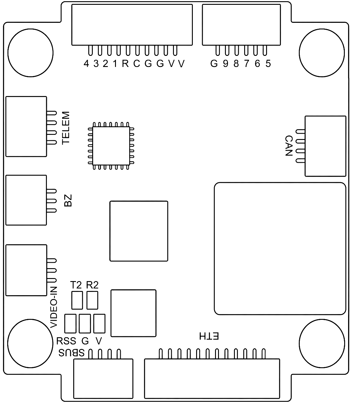
Refer to the Godwit G-FH7 product page and the Godwit G-FH7 datasheet for the latest board information and interface definition.
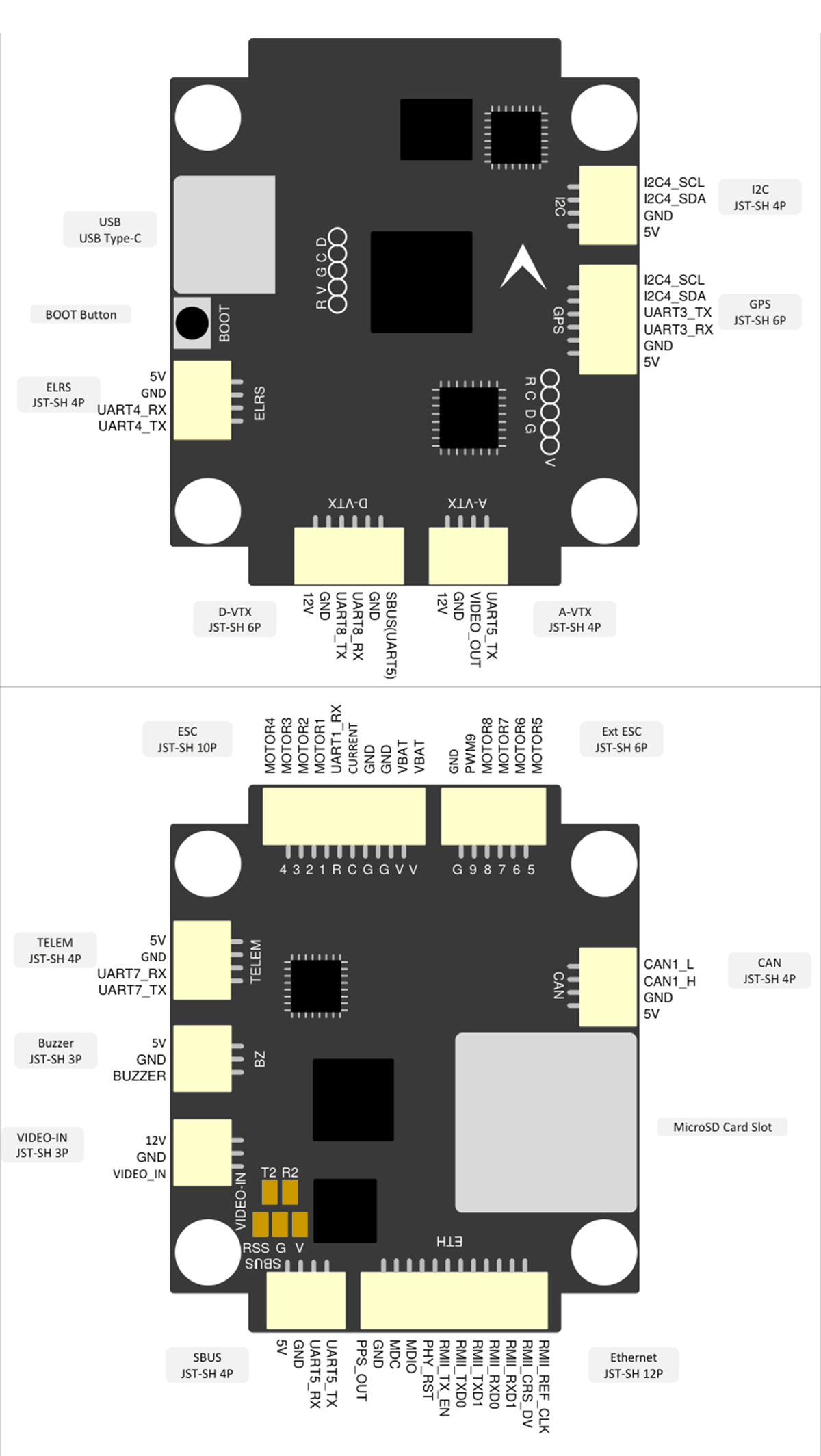
Interface Summary
| Interface | Function |
|---|---|
ESC / Ext ESC | Connect the ESC and motor system. |
GPS | Connect a GPS module. |
SBUS / ELRS | Connect an RC receiver. |
TELEM | Connect a telemetry radio or MAVLink device. |
CAN | Connect CAN peripherals. |
I2C | Connect external I2C sensors. |
BZ | Connect an external active buzzer. |
VIDEO-IN | Connect an analog camera. |
A-VTX / D-VTX | Connect an analog or digital video transmitter. |
Block Diagram
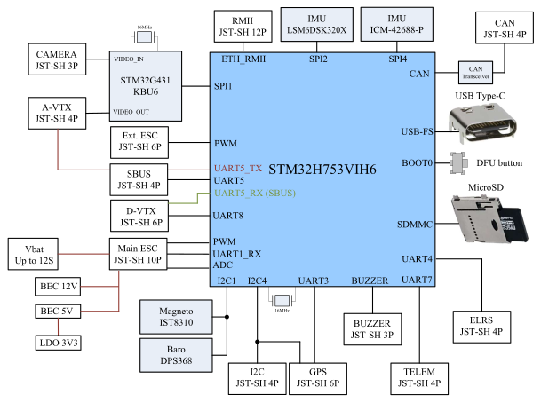
The block diagram below shows the main components (sensors and power supply) and how they connect to the STM32H753 FMU.
Power
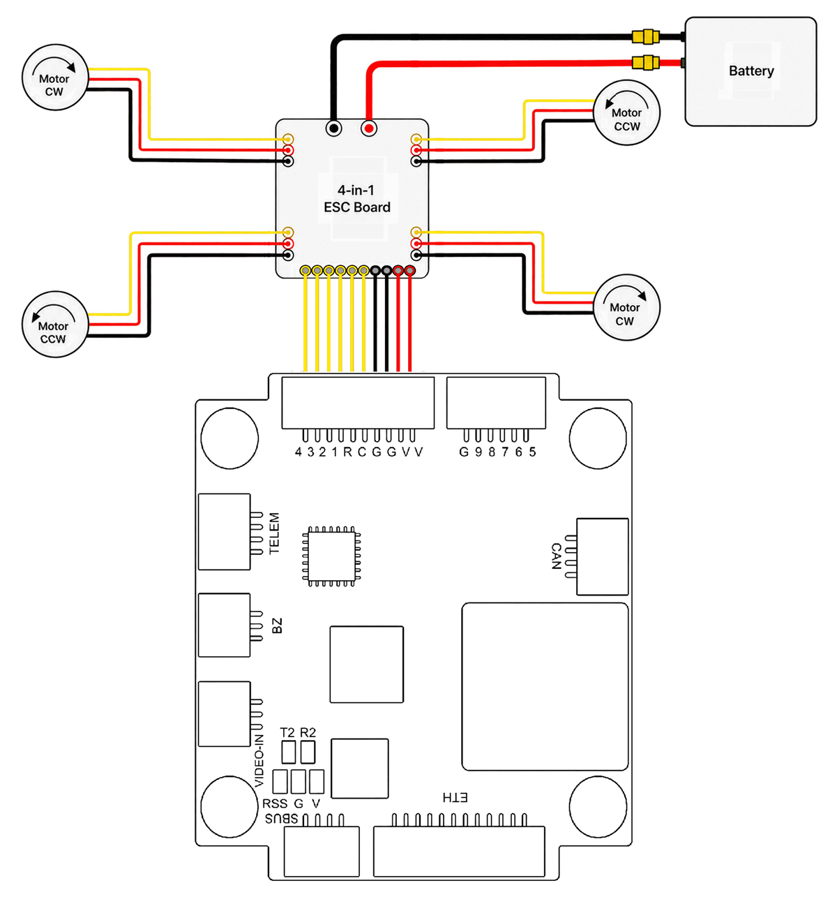
The board is powered from the battery through the VBAT pins on the ESC connector (JST-SH 10P), which also carries the ESC's battery current signal (CURRENT pin). Onboard BECs supply 5V/3A and 12V/3A to peripherals.
The 12V output is on at boot. To switch it from your transmitter, assign an RC switch to RC_MAP_PAY_SW: the 12V output then stays off until the switch is set to on.
Battery voltage monitoring is configured by default (BAT1_V_DIV is set to 17.0). Current monitoring depends on the ESC's current sensor, so you must set BAT1_A_PER_V as described in Battery and Power Module Setup.
Voltage Ratings
The board can be powered from the battery input (VBAT pins on the ESC connector) or from USB.
Normal Operation Maximum Ratings
Under these conditions all power sources will be used in this order to power the system:
- Battery input (up to 12S LiPo, 50.4V maximum)
- USB input (4.75V to 5.25V)
Absolute Maximum Ratings
Under these conditions the system will not draw any power (will not be operational), but will remain intact.
- Battery input (65V)
INFO
The flight controller keeps working below 13V on the battery input. The 12V output for the camera and video transmitter (VTX) is generated from the battery input and needs about 13V or more to stay at 12V. Below that, the camera and VTX lose power.
PWM Outputs
The board has 8 PWM outputs, on the MOTOR1-MOTOR8 pins of the ESC and Ext ESC connectors. All 8 outputs support DShot and bidirectional DShot.
The outputs are in 2 groups:
- Outputs 1-4 in group 1 (Timer1)
- Outputs 5-8 in group 2 (Timer8)
All outputs within the same group must use the same output protocol and rate.
The PWM9 pin on the Ext ESC connector drives a NeoPixel (WS2812-compatible) LED strip of up to 8 LEDs, and can't be used as an actuator output.
SD Card (Optional)
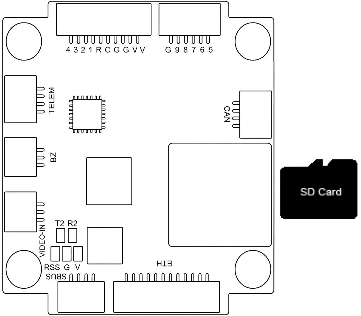
The board has a microSD card slot, which PX4 uses for flight logs and other data. See SD Cards for more information.
IMU Heater
The board has a resistive IMU heater, which draws about 67mA (0.33W, calculated from the heater resistor value) from the 5V supply.
The heater is off by default. To enable it, set SENS_EN_THERMAL to 1 and reboot. The target temperature is set by HEATER1_TEMP, which this board sets to 45°C.
If you enable the heater, run the accelerometer calibration only after heater status (in the MAVLink Shell) shows that the sensor temperature has reached the target temperature.
Serial Port Mapping
| UART | Device | Port | Connector |
|---|---|---|---|
| USART1 | /dev/ttyS0 | EXT2 | ESC (ESC telemetry, RX only) |
| USART2 | /dev/ttyS1 | TELEM 2 | T2/R2 solder pads |
| USART3 | /dev/ttyS2 | GPS 1 | GPS |
| UART4 | /dev/ttyS3 | TELEM/SERIAL 4 | ELRS (CRSF by default) |
| UART5 | /dev/ttyS4 | Radio Controller | SBUS (RX and TX), A-VTX (TX, not used), D-VTX (SBUS pin, RX) |
| UART7 | /dev/ttyS5 | TELEM 1 | TELEM |
| UART8 | /dev/ttyS6 | TELEM 3 | D-VTX |
EXT2 is receive-only, so it can't be used for MAVLink or other two-way protocols. It reads ESC telemetry from the ESC connector (DSHOT_TEL_CFG is set to EXT2 by default).
No ports have flow control.
INFO
The bootloader enables only UART7 (the TELEM connector), so TELEM is the only serial port px4_uploader.py can flash firmware over.
Assembly
Wiring Diagrams
Refer to the Godwit G-FH7 product page and the Godwit G-FH7 datasheet for the latest wiring and connector information.
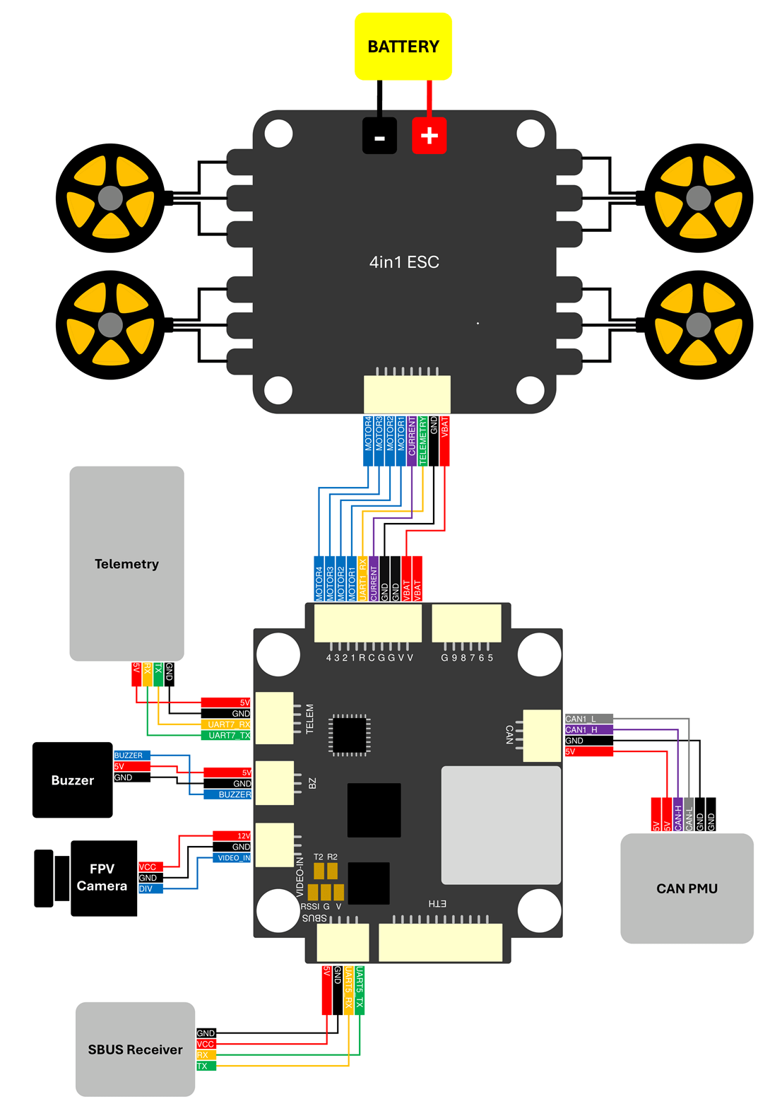
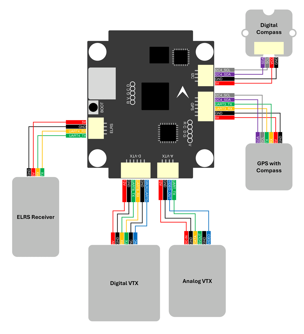
The diagram below shows how to connect a 4-in-1 ESC and its motors to the ESC connector.
Radio Control
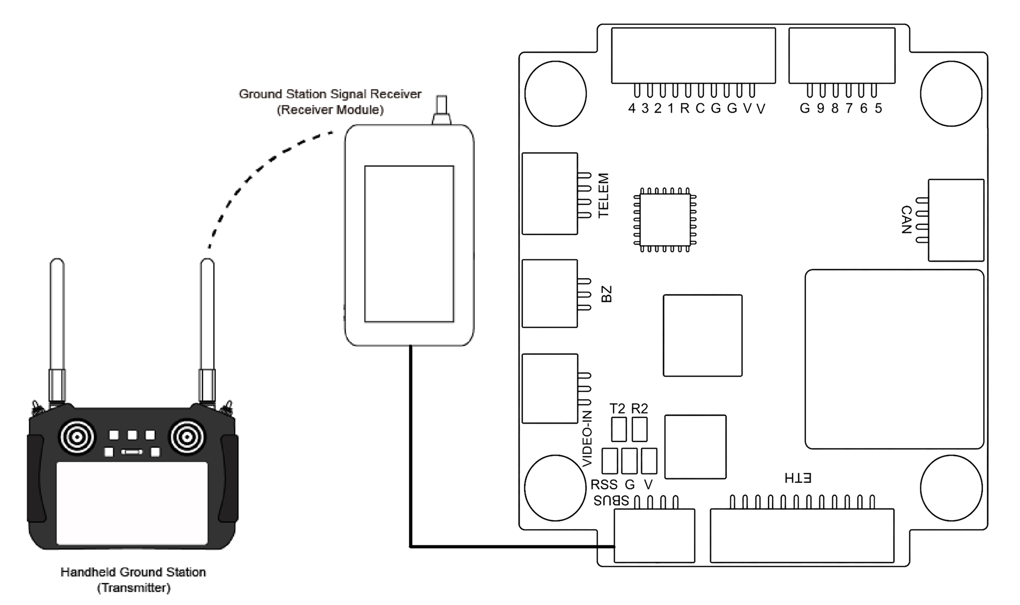
A remote control (RC) radio system is required if you want to manually control your vehicle (PX4 does not require a radio system for autonomous flight modes). See Radio Control Systems for how to select a transmitter/receiver.
The board has two receiver connectors (JST-SH 4P), both wired to FMU UARTs:
ELRS(UART4, PX4 portTELEM/SERIAL 4): CRSF/ExpressLRS is enabled on this port by default (RC_CRSF_PRT_CFG is set toTELEM/SERIAL 4). CRSF telemetry to the transmitter is also enabled by default (RC_CRSF_TEL_EN).SBUS(UART5, PX4 portRadio Controller): for S.BUS receivers. To use it, set RC_SBUS_PRT_CFG toRadio ControllerandRC_CRSF_PRT_CFGtoDisabled. The connector is wired to bothUART5_RXandUART5_TX. TheSBUSpin on theD-VTXconnector shares theUART5_RXline, for digital video systems that output S.BUS. The TX pin on theA-VTXconnector shares theUART5_TXline, but PX4 doesn't use this pin.
The other built-in protocols, DSM and GHST (TBS Ghost), are enabled by setting RC_DSM_PRT_CFG or RC_GHST_PRT_CFG to the port the receiver is connected to, and RC_CRSF_PRT_CFG to Disabled. DSM receivers can't be bound from PX4 or QGroundControl on this board, so bind the receiver using its own bind procedure. The ELRS and SBUS connectors supply 5V, so power a 3.3V DSM receiver from a separate 3.3V supply. Only one protocol can be active on a port. PPM receivers are not supported, so PWM receivers can't be used either, even with a PPM encoder.
The vehicle boots in Stabilized mode (multicopter, fixed-wing) instead of the PX4 default of Hold mode (COM_FLTMODE_BOOT is set to Stabilized). A flight mode switch, if you assign one with RC_MAP_FLTMODE, overrides this.
GPS & Compass
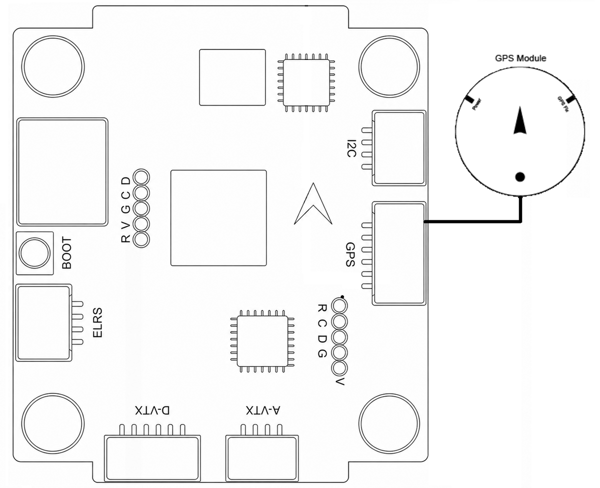
Connect a GPS/compass module to the GPS connector (JST-SH 6P), which carries USART3 (PX4 port GPS 1) and the external I2C bus (I2C4) for the compass. See Mounting the GPS/Compass for placement.
An external compass (usually built into the GPS module) is recommended over the onboard iSentek IST8310, because it can be mounted away from motors and power wiring.
Telemetry Radios (Optional)
Connect the radio to the TELEM connector (PX4 port TELEM 1), which is configured for MAVLink by default.
Telemetry radios are used to provide a wireless data link between the vehicle and a ground control station (GCS) such as QGroundControl. This allows you to monitor flight data, change missions in real time, and receive in-flight status updates. See Telemetry Radios.
CAN
The CAN connector (JST-SH 4P) is used for DroneCAN peripherals such as GPS modules, ESCs, and sensors. DroneCAN is disabled by default: enable it by setting UAVCAN_ENABLE.
OSD
The board has an analog OSD co-processor (AT7456-compatible), which is enabled by default in NTSC mode. Connect the camera to VIDEO-IN and the analog video transmitter to A-VTX. PX4 doesn't use the TX pin on the A-VTX connector, so VTX control (SmartAudio/Tramp) is not supported on this board. Set OSD_ATXXXX_CFG to 2 for PAL, or 0 to disable the OSD, and reboot.
For a digital video transmitter on the D-VTX connector, set MSP_OSD_CONFIG to TELEM 3 to enable MSP OSD.
Building Firmware
TIP
From PX4 v2.0, most users will not need to build this firmware! It is pre-built and automatically installed by QGroundControl when appropriate hardware is connected.
The board ships with the PX4 bootloader.
To build PX4 for this target from source:
make accton-godwit_gfh7_defaultFor a debug build with the system console enabled (accton-godwit_gfh7_debug), see Debug Port.
Debug Port
The top face has two unpopulated five-pad test/debug groups for manufacturing, debugging, or hardware verification. They don't follow the Pixhawk Debug connector standards, so a debug probe must be wired to the pads directly.
The R V G C D pad group is the SWD interface of the STM32H753 FMU:
| Pad | Signal | Voltage |
|---|---|---|
R | ST_RST_L | 3.3V |
V | VDD3V3 | 3.3V |
G | GND | GND |
C | FMU_SWCLK | 3.3V |
D | FMU_SWDIO | 3.3V |
The R C D G V pad group is the SWD interface of the OSD co-processor (STM32G431), which PX4 doesn't use:
| Pad | Signal | Voltage |
|---|---|---|
R | OSD_NRST | 3.3V |
C | G431_SWCLK | 3.3V |
D | G431_SWDIO | 3.3V |
G | GND | GND |
V | VDD3V3 | 3.3V |
These pads are not general user interfaces: only connect an SWD debug probe to them, and do not apply power to them or use them as GPIO, UART, or I2C interfaces.
The default firmware does not provide a serial System Console. Use the MAVLink Shell over USB or a telemetry link instead.
The debug build enables the system console on UART4 (the ELRS connector):
make accton-godwit_gfh7_debugTELEM/SERIAL 4 is not available in that build, so the ELRS connector can't be used for a receiver. To use an S.BUS receiver on the SBUS connector instead, set RC_SBUS_PRT_CFG to Radio Controller.
Further Information
- Accton-IoT Godwit G-FH7 (product page)
- Godwit G-FH7 documentation
- Godwit G-FH7 datasheet
- Sales: sales@accton-iot.com
- Support: support@accton-iot.com