
Avian Automata 305AP
main (PX4 v2.0)WARNING
PX4 does not manufacture this (or any) autopilot. Contact the manufacturer for hardware support or compliance issues.
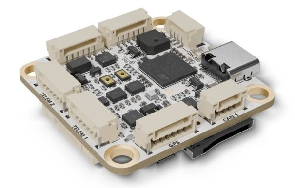
The 305AP is a compact flight controller designed by Avian Automata. It is built around the STM32H743 processor with two IMU slots, an onboard barometer and magnetometer, two CAN buses, and eight motor outputs.
INFO
This flight controller is manufacturer supported.
Specifications
Processor
- Main FMU processor: STM32H743VIH6 (32-bit Arm® Cortex®-M7, 480 MHz, 2 MB flash, 1 MB RAM)
Sensors
- IMU: 2 slots (SPI2, SPI3), each fitted with either an ST LSM6DSV16X or a TDK InvenSense ICM-45686 (detected at boot)
- Barometer: Bosch BMP581 (SPI1)
- Magnetometer: MEMSIC MMC5983MA (I2C1)
Interfaces
- PWM outputs: 8, all supporting DShot
- Serial ports: 7 (
TELEM 1,TELEM 2,GPS,RC IN,VTX, the debug console onVTX, and ESC telemetry on theMotorsconnector) - I2C buses: 3 (I2C1 internal; I2C2 and I2C4 external, I2C4 on the
GPSconnector) - SPI buses: 4, of which SPI4 is external with 2 chip selects
- CAN buses: 2 (FDCAN1, FDCAN2)
- USB: USB-C (USB 2.0 Full Speed)
- RC input: Yes
- Parameter storage: microSD card
- SD card: microSD slot
- OSD: MSP OSD on
VTX
Electrical Data
- Input voltage: 2S-6S (6.4 V to 25.2 V)
- Power monitoring: 1 analog battery voltage input, plus an analog current sense input (no onboard current shunt)
- Power outputs: regulated 5 V and 9 V (9 V at battery voltage on 2S)
Mechanical Data
- Dimensions: 36.5 mm x 36.5 mm
- Weight: 11 g (with microSD card)
- Mounting hole spacing: 30.5 mm x 30.5 mm, M4 holes sized for M3 rubber vibration isolators
Where to Buy
Order from the Avian Automata store.
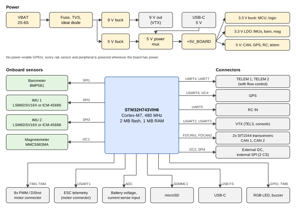
Block Diagram
Pinouts
All connectors are JST-GH. Pin 1 is marked on each connector housing.
Power (CN1)
| Pin | Signal |
|---|---|
| 1-3 | VBAT_IN |
| 4-6 | GND |
TELEM 1 (CN2) and TELEM 2 (CN3)
| Pin | Signal | TELEM 1 (UART4) | TELEM 2 (UART7) |
|---|---|---|---|
| 1 | +5V | ||
| 2 | TX | PA0 | PE8 |
| 3 | RX | PA1 | PE7 |
| 4 | CTS | PB0 | PE10 |
| 5 | RTS | PB14 | PE9 |
| 6 | GND |
GPS (CN4)
This is a 6-pin port, not the 10-pin Pixhawk GPS port.
| Pin | Signal | MCU |
|---|---|---|
| 1 | +5V | |
| 2 | UART TX | PC6 |
| 3 | UART RX | PC7 |
| 4 | I2C4 SCL | PD12 |
| 5 | I2C4 SDA | PD13 |
| 6 | GND |
CAN 1 (U18) and CAN 2 (U19)
| Pin | Signal |
|---|---|
| 1 | +5V |
| 2 | CAN_H |
| 3 | CAN_L |
| 4 | GND |
External I2C (U20)
| Pin | Signal | MCU |
|---|---|---|
| 1 | +5V | |
| 2 | I2C2 SCL | PB10 |
| 3 | I2C2 SDA | PB11 |
| 4 | GND |
External SPI (CN7)
| Pin | Signal | MCU |
|---|---|---|
| 1 | +5V | |
| 2 | SPI4 SCK | PE2 |
| 3 | SPI4 MISO | PE13 |
| 4 | SPI4 MOSI | PE6 |
| 5 | CS1 | PC13 |
| 6 | CS2 | PC14 |
| 7 | GND |
The firmware includes the MS5611 barometer and PMW3901 optical flow drivers for sensors on this port, but doesn't start them. To use one, start it from extras.txt on the SD card, for example ms5611 -S -b 1 -c 2 start for an MS5611 on CS2.
Motors (U21)
| Pin | Signal | MCU | Timer |
|---|---|---|---|
| 1 | +5V | ||
| 2 | Current sense | PC3 | |
| 3 | ESC telemetry | PA9 | |
| 4 | Motor 1 | PA8 | TIM1 CH1 |
| 5 | Motor 2 | PE11 | TIM1 CH2 |
| 6 | Motor 3 | PA15 | TIM2 CH1 |
| 7 | Motor 4 | PA2 | TIM2 CH3 |
| 8 | Motor 5 | PA7 | TIM3 CH2 |
| 9 | Motor 6 | PB1 | TIM3 CH4 |
| 10 | Motor 7 | PB7 | TIM4 CH2 |
| 11 | Motor 8 | PD14 | TIM4 CH3 |
| 12 | GND |
VTX (CN6)
| Pin | Signal | MCU |
|---|---|---|
| 1 | +9V | |
| 2 | GND | |
| 3 | UART TX | PD5 |
| 4 | UART RX | PD6 |
| 5 | GND | |
| 6 | SBUS out | PD8 |
RC IN (U22)
| Pin | Signal | MCU |
|---|---|---|
| 1 | +5V | |
| 2 | RC_IN | PB13 |
| 3 | GND |
Power
The board is powered from the battery on the 6-pin JST-GH Power connector (2S-6S), or from USB-C. The board has no power-enable GPIOs: every rail, sensor and peripheral is powered whenever the board has power, except the 9 V rail, which needs battery power.
Battery monitoring is analog. The board measures battery voltage with a 10k/1k divider (BAT1_V_DIV defaults to 11.0). There is no onboard current shunt. To measure current, connect an external sensor to the current sense pin on the Motors connector and set BAT1_A_PER_V, which defaults to 0 (see Amps per volt). See Battery and Power Module Setup for configuration.
The board can't sense its 5 V rail or detect USB VBUS, so the arming power-supply check is disabled (CBRK_SUPPLY_CHK defaults to 894281).
Voltage Ratings
Powerinput: 2S-6S, 6.4 V to 25.2 V (35 V DC absolute maximum)- USB input: 5 V nominal (5.5 V recommended maximum, 6 V absolute maximum)
PWM Outputs
The 8 outputs are in 4 groups:
- Outputs 1-2 in group 1 (TIM1)
- Outputs 3-4 in group 2 (TIM2)
- Outputs 5-6 in group 3 (TIM3)
- Outputs 7-8 in group 4 (TIM4)
All outputs support PWM and DShot, and default to DShot300 (PWM_MAIN_TIM0 to PWM_MAIN_TIM3 = -4). The firmware also supports bidirectional DShot on all outputs, but it hasn't yet been verified on this board. All outputs in a group must use the same protocol and rate.
SD Card (Optional)
The board has a push-push microSD card slot on the bottom. Parameters are stored on the card, so they can't be saved without one. For information about choosing and using an SD card see SD Cards (Removable Memory).
Serial Port Mapping
| UART | Device | Port | Connector | Flow Control |
|---|---|---|---|---|
| USART1 | /dev/ttyS0 | ESC telemetry | Motors (pin 3) | |
| USART2 | /dev/ttyS1 | TELEM 3 | VTX | |
| USART3 | /dev/ttyS2 | Debug Console | VTX (SBUS out pin) | |
| UART4 | /dev/ttyS3 | TELEM 1 | TELEM 1 | Yes |
| UART5 | /dev/ttyS4 | Radio Controller | RC IN | |
| USART6 | /dev/ttyS5 | GPS 1 | GPS | |
| UART7 | /dev/ttyS6 | TELEM 2 | TELEM 2 | Yes |
ESC telemetry from Motors pin 3 (USART1) is enabled by default, so leave DSHOT_TEL_CFG at Disabled.
INFO
The bootloader enables no UART, so firmware can only be flashed over USB.
Assembly
Radio Control
A remote control (RC) radio system is required if you want to manually control your vehicle (PX4 does not require a radio system for autonomous flight modes). You will need to select a compatible transmitter/receiver and then bind them so that they communicate.
Connect the receiver to the 3-pin JST-GH RC IN connector, a single-wire port on the FMU (UART5, /dev/ttyS4).
- S.BUS, DSM, SUMD, ST24, CRSF and GHST receivers are detected automatically, with no configuration (RC_INPUT_PROTO =
Auto). - PPM receivers are not supported, so PWM receivers can't be connected through a PPM encoder either.
- DSM receivers can't be bound from QGroundControl on this board: bind them before connecting.
- CRSF telemetry back to the transmitter needs a full-duplex port, so connect those receivers to
TELEM 1orTELEM 2instead. Set RC_CRSF_PRT_CFG to that port and RC_CRSF_TEL_EN to1, then reboot. OnTELEM 1, also set MAV_0_CONFIG toDisabled, since MAVLink uses it by default.
The DSM, GHST and S.BUS drivers can also be run on another serial port, using RC_DSM_PRT_CFG, RC_GHST_PRT_CFG or RC_SBUS_PRT_CFG. Only one protocol can be active on a port.
GPS & Compass
The 6-pin JST-GH GPS connector carries GPS (USART6) and I2C (I2C4) for the compass in a GPS module. It has no safety switch, buzzer or LED signals.
The board has an onboard MMC5983MA magnetometer. The +5V pins on all connectors come from the board's 5 V rail, so a load on them that varies in flight (servos, a companion computer, a video transmitter) can upset the onboard compass. On such vehicles, use an external compass in a GPS module. See Mounting a GPS/Compass for more information.
Telemetry Radios (Optional)
The board has two telemetry ports, TELEM 1 and TELEM 2, each a 6-pin JST-GH connector with flow control. A telemetry radio connected to TELEM 1 needs no further configuration.
CAN
The board has two CAN ports, CAN 1 and CAN 2, each a 4-pin JST-GH connector, for DroneCAN peripherals. Both buses are fully terminated on the board, so do not add external termination.
DroneCAN is not enabled by default: set UAVCAN_ENABLE to enable it.
OSD
Connect the video transmitter to the 6-pin JST-GH VTX connector, which carries 9 V power, a UART (USART2) and the SBUS out pin. MSP OSD runs on this UART (TELEM 3) by default, at 115200 baud (MSP_OSD_CONFIG = TELEM 3, SER_TEL3_BAUD = 115200). The 9 V rail is only available when the board is powered from the battery, and runs at battery voltage on 2S.
WARNING
Pin 6 (SBUS out) carries the PX4 System Console output. If your air unit's cable has an SBUS wire, leave it unconnected.
Building Firmware
TIP
From PX4 v2.0, most users will not need to build this firmware! It is pre-built and automatically installed by QGroundControl when appropriate hardware is connected.
To build PX4 for this target:
make avianautomata_305ap_defaultThe board also has a rover build variant: avianautomata_305ap_rover.
Debug Port
The FMU's PX4 System Console output is on USART3 TX (PD8) at 57600 baud, the SBUS out pin of the VTX connector. The port is transmit-only, so use the MAVLink Shell over USB for an interactive console.
The SWD interface isn't brought out: its pins (PA13 and PA14) are used by the second IMU slot.