
Freefly Systems RTK GPS
The Freefly Systems RTK GPS Module is a multiband RTK GPS module from Freefly Systems that provides highly reliable navigation. The modules can act as either rovers (when installed on an aircraft) or base stations (when plugged into a computer).
Main features include:
- Multiband (L1/L2) receiver (u-blox ZED-F9P)
- Concurrent reception of all 4 GNSS (GPS, Galileo, GLONASS, BeiDou)
- Built-in magnetometer (IST8310), baro (BMP388), RGB LED, safety switch and safety LED
INFO
This module can be used with PX4 v1.9 or above (support for the u-blox ZED-F9P was added in PX4 v1.9).
Where to Buy
Kit Contents
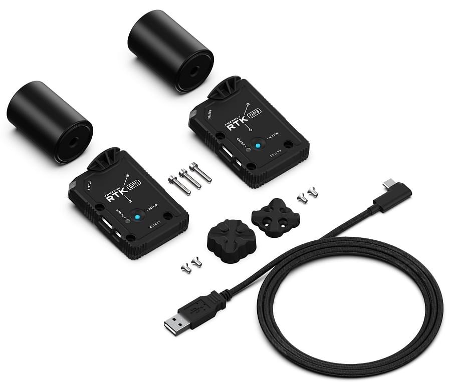
An RTK GPS kit includes:
- 2x GPS modules with antennas
- 3m USB C to A cable
- Magnetic quick-mount for base station module (1/4-20 thread for tripod mounting)
- Screws to mount onto a Freefly AltaX
Configuration
RTK setup and use on PX4 via QGroundControl is largely plug and play (see RTK GPS for more information).
For the aircraft, you should set the parameter SER_GPS1_BAUD to 115200 8N1 to ensure that PX4 configures the correct baudrate.
Wiring and Connections
The Freefly RTK GPS comes with an 8 pin JST-GH connector that can be plugged into a PixHawk autopilot. For use as a base station, the module has a USB-C connector
Pinout
The Freefly GPS pinout is provided below. For some autopilots, like the Hex Cube and PixRacer, all that is needed is a 1-1 8-pin JST-GH cable.
| Pin | Freefly GPS |
|---|---|
| 1 | VCC_5V |
| 2 | GPS_RX |
| 3 | GPS_TX |
| 4 | I2C_SCL |
| 5 | I2C_SDA |
| 6 | BUTTON |
| 7 | BUTTON_LED |
| 8 | GND |
Specification
- u-blox ZED-F9P GPS Receiver
- Ultracap backup power for fast (hot-start) restarts
- EMI shield over receiver for improved EMI immunity
- IST8310 Magnetometer
- Safety-switch and safety LED
- RGB LEDs for status indication
- NCP5623CMUTBG I2C Driver
- BMP388 Baro on I2C bus
- External, active antenna (Maxtena M7HCT)
- SMA connector
- STM32 MCU for future CAN-based communication
- FW updates through USB connector
- Connectivity:
- USB-C
- 2-way USB Switch to MCU and F9P
- SMA for active antenna (20mA max)
- 4-pin JST-GH CAN Bus (dronecode compliant)
- 8-pin JST-GH UART/I2C -** Power:
- Input from either (diode OR'd):
- USB (5V)
- CAN (4.7 to 25.2V)
- (4.7 to 25.2V)
- Power consumption <1W
More Information
More information can be found on Freefly's Wiki