
NXP MR-VMU-TROPIC
PX4 v1.17WARNING
PX4 does not manufacture this (or any) autopilot. Contact the manufacturer for hardware support or compliance issues.
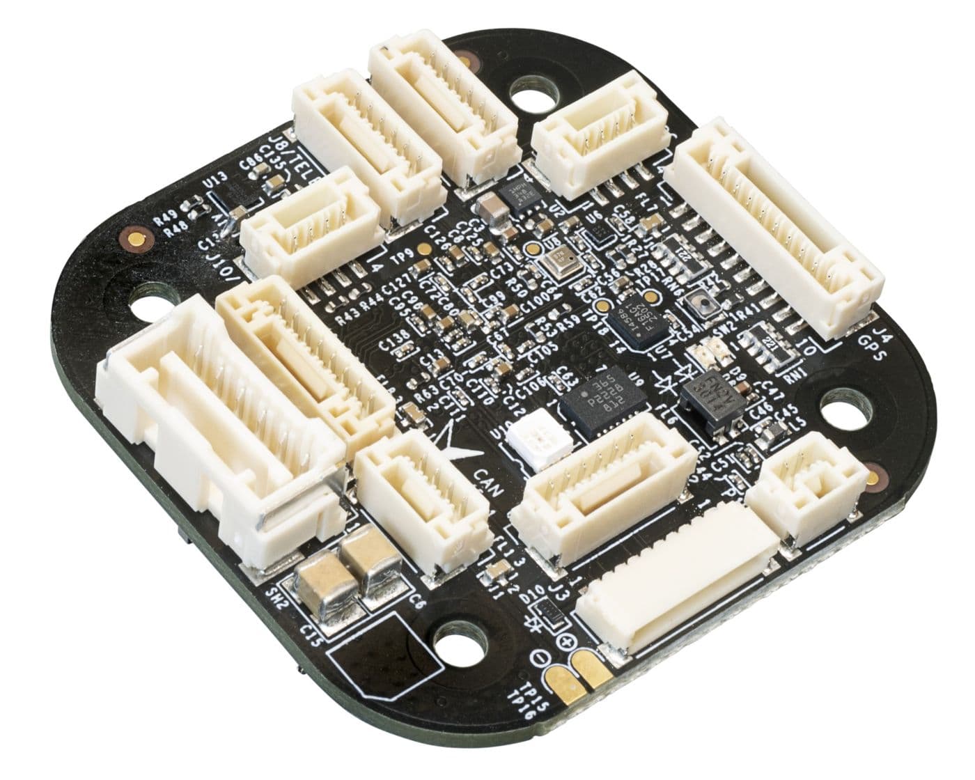
The MR-VMU-TROPIC is NXP's open source reference design of a versatile VMU that can be used for drones, rovers, boats, and more. As a reference/evaluation design, it is intended to be replicated, modified or integrated in production volume by others. Since it is a reference design, this particular board is not produced in high volume. Similar variants will be available from NXP licensees.
The board combines an NXP i.MX RT1064 with sensor technology from Bosch® and InvenSense® on one compact board. It is suitable for controlling any autonomous vehicle, in both academic and commercial applications. The high-performance, low-noise IMUs are designed for better stabilisation.
Besides the standard interfaces, it has 100BASE-T1 (two-wire) automotive Ethernet and 8 PWM outputs, all with DShot.
The MR-VMU-TROPIC reference design suits developers at corporate research labs, startups, academia and commercial companies who want to try out 100BASE-T1 (two-wire) automotive Ethernet.
INFO
This flight controller is manufacturer supported.
Specifications
Processor
- Main FMU processor: NXP i.MX RT1064 Crossover MCU (32-bit Arm® Cortex®-M7 at 600MHz, 1MB on-chip SRAM with up to 512KB configurable as tightly coupled memory, 4MB on-chip flash)
Sensors
- IMU: TDK InvenSense ICM-45686 (SPI3), Bosch BMI088 (SPI4). Hardware versions with a TDK InvenSense ICM-42686-P in place of the ICM-45686 are supported from PX4 v2.0 (currently
main). - Barometer: Bosch BMP390 (I2C4)
- Magnetometer: Bosch BMM350 (I2C4)
Interfaces
- PWM outputs: 8, all with DShot and bidirectional DShot
- Serial ports: 5 (
GPS,TELEM1,TELEM2,AUX,RC), plus the debug console and an ESC telemetry input;TELEM1andTELEM2have full flow control - I2C buses: 3 (I2C4 internal; I2C1 and I2C3 external), with 1 external port (
I2C) for additional sensors and payloads - SPI buses: 2 internal (SPI3, SPI4), plus 1 external (
SPI (OSD)) with 1 chip select line, 1 data-ready line and 1 reset line, not used by the default firmware - CAN buses: 1 (classic CAN in PX4; CAN FD-capable NXP TJA1462ATK transceiver, 120Ω termination resistor on board)
- Ethernet: 100BASE-T1, 100Mbps, for transformerless applications and high-speed communication with mission computers (NXP TJA1103 PHY)
- USB: USB-C, high speed (480Mbps)
- RC input: Yes, dedicated input for CRSF/ELRS
- Parameter storage: flash
- SD card: microSD slot
Electrical Data
- Input voltage: 5.5V maximum
- USB power input: 5V
- Current draw: typically 0.25–0.35A at 5V
- Power monitoring: 1 digital input on
POWER(INA226 at0x41, or INA228 or INA238 at0x45, detected automatically); no analog input
Mechanical Data
- Dimensions: 46 x 45 x 1.57mm
- Weight: 12g
- Operating and storage temperature: 0–85°C
Where to Buy
Order from NXP.
Pinouts
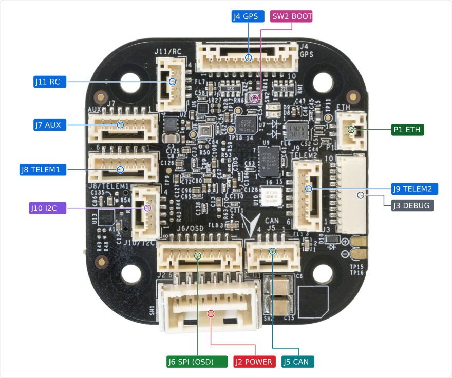
The TELEM1, TELEM2, GPS, I2C, CAN and DEBUG connectors follow the Pixhawk Connector Standard (DS-009). The ESC headers (PWM_A and PWM_B) follow the Betaflight ESC connector standard.
The pinout of every connector is given in NXP's MR-VMU-TROPIC hardware reference (also as a PDF and a one-page cheat sheet). The schematic is SPF-94468_F.pdf (rev F).
Top Side Connectors
| Connector | Label | Function | Type | Standard |
|---|---|---|---|---|
J2 | POWER | Power module input: 5V and battery monitor I2C | Molex CLIK-Mate 1x6 | — |
J3 | DEBUG | SWD and console | JST-SH 1x10 | DS-009 (Debug Full) |
J4 | GPS | GPS, compass, safety switch and buzzer | JST-GH 1x10 | DS-009 |
J5 | CAN | CAN FD, CAN-SIC (Signal Improvement) transceiver, 120Ω termination | JST-GH 1x4 | DS-009 |
J6 | SPI (OSD) | External SPI port for an OSD board | JST-GH 1x8 | — |
J7 | AUX | Spare serial port | JST-GH 1x6 | — |
J8 | TELEM1 | Telemetry port 1, with flow control | JST-GH 1x6 | DS-009 |
J9 | TELEM2 | Telemetry port 2, with flow control | JST-GH 1x6 | DS-009 |
J10 | I2C | External I2C bus, shared with GPS | JST-GH 1x4 | DS-009 |
J11 | RC | Serial RC receiver | JST-GH 1x4 | — |
P1 | ETH | 100BASE-T1 100Mbps Ethernet | JST-GH 1x2 | — |
Bottom Side Connectors
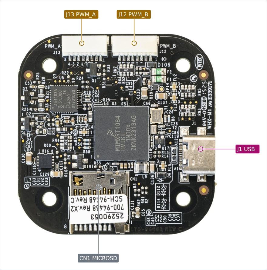
| Connector | Label | Function | Type | Standard |
|---|---|---|---|---|
J1 | USB | USB 2.0 device port | USB-C | — |
J12 | PWM_B | Motor outputs 5–8 (ESC header) | JST-SH 1x8 | Betaflight ESC |
J13 | PWM_A | Motor outputs 1–4 (ESC header) | JST-SH 1x8 | Betaflight ESC |
CN1 | MICROSD | microSD card slot | microSD, push-push | — |
Power
The board has two power rails: POWER and USB. The POWER rail is supplied via the J2 connector (the 6-circuit 2.00mm pitch CLIK-Mate wire-to-board PCB receptacle) and directly powers the following ports: I2C (J10), GPS (J4), AUX (J7), CAN (J5), TELEM1 (J8), TELEM2 (J9), RC (J11) and SPI (OSD) (J6).
WARNING
Feed only 5V into POWER (J2): there is no regulator behind this connector, and a higher voltage damages the board. Every other 5V pin on the board is an output: never feed power into it. Any device connected to the ports listed above must be compatible with the POWER voltage rail.
Battery monitoring is digital, over I2C (I2C3 on the POWER port). Any power module with an INA226 at address 0x41, or an INA228 or INA238 at 0x45, is detected automatically. To start a specific one instead, set SENS_EN_INA226, SENS_EN_INA228 or SENS_EN_INA238 to 1.
INFO
Analog battery monitoring via an ADC is not supported on this board.
See Battery and Power Module Setup for configuration.
Voltage Ratings
Normal Operation Maximum Ratings
| Rail | Minimum | Maximum |
|---|---|---|
| USB | 4.5V | 5.5V |
| POWER | 4.9V | 5.5V |
Absolute Maximum Ratings
| Rail | Minimum | Maximum |
|---|---|---|
| USB | 0V | 6V |
| POWER | 0V | 6V |
PWM Outputs
The board has 8 PWM outputs. All of them support DShot and bidirectional DShot.
The outputs are divided into 4 groups:
- Outputs 1-2
- Outputs 3-4
- Outputs 5-6
- Outputs 7-8
All outputs within the same group must use the same output protocol and rate.
Outputs 1–4 are on PWM_A (J13) and outputs 5–8 on PWM_B (J12). Both headers follow the Betaflight ESC connector standard, so a 4-in-1 ESC with a standard 8-pin cable fits. The headers have no 5V pin, and their battery voltage and current pins (1 and 3) are not connected: the board doesn't use the ESC's BEC or read battery voltage or current from the ESC.
Serial ESC telemetry is received on pin 4 of both headers (/dev/ttyS5, ESC ONEWIRE) and is enabled by default.
Ethernet
The P1 port provides 100BASE-T1 Ethernet. The other end needs a 100BASE-T1 device or a media converter. MAVLink runs on Ethernet by default, using UDP port 14550 (MAV_2_CONFIG is set to Ethernet).
See PX4 Ethernet Setup for more information.
SD Card (Optional)
The microSD card slot (CN1) is on the bottom of the board. See SD Cards (Removable Memory).
Serial Port Mapping
| UART | Device | Port | Flow Control |
|---|---|---|---|
| LPUART6 | /dev/ttyS0 | DEBUG | No |
| LPUART2 | /dev/ttyS1 | GPS | No |
| LPUART3 | /dev/ttyS2 | TELEM1 | Yes |
| LPUART4 | /dev/ttyS3 | AUX | No |
| LPUART5 | /dev/ttyS4 | TELEM2 | Yes |
| LPUART7 | /dev/ttyS5 | ESC ONEWIRE | No |
| LPUART8 | /dev/ttyS6 | RC | No |
INFO
The AUX port is TELEM 3 in the serial port configuration.
Assembly
Radio Control
A remote control (RC) radio system is required if you want to manually control your vehicle (PX4 does not require a radio system for autonomous flight modes). You will need to select a compatible transmitter/receiver and then bind them so that they communicate.
Connect the receiver to the RC port (J11, JST-GH 4-pin), which is the FMU serial port /dev/ttyS6. CRSF receivers are enabled on this port by default, with telemetry.
The default firmware also includes DSM, GHST and S.BUS drivers. To use one of these protocols, set RC_CRSF_PRT_CFG to Disabled, and then set RC_DSM_PRT_CFG, RC_GHST_PRT_CFG or RC_SBUS_PRT_CFG to Radio Controller. Only one protocol can be active on a port.
DSM binding is not supported: receivers must already be bound. PPM receivers are not supported, because RC is a serial port. PWM receivers, which need a PPM encoder, can't be used either.
GPS & Compass
Connect the GPS module to the GPS port (J4, Pixhawk standard), which carries the GPS serial port (/dev/ttyS1) and the I2C1 bus for an external compass. The port also carries the safety switch and its LED, and the buzzer. The I2C port (J10) is on the same I2C bus, so devices on the two ports need different addresses. The board also has an internal Bosch BMM350 magnetometer.
See Mounting the GPS/Compass for more information.
Telemetry Radios (Optional)
Telemetry radios can be connected to any free serial port, such as TELEM1 (J8), TELEM2 (J9) or AUX (J7). TELEM1 is configured for MAVLink by default and needs no further configuration. To use another port, see MAVLink Peripherals.
CAN
Connect DroneCAN peripherals to the CAN port (J5). DroneCAN is disabled by default; enable it with UAVCAN_ENABLE.
PX4 Bootloader Update
NXP's PX4 setup guide says that a board that doesn't come with the PX4 bootloader needs it flashed before PX4 can be installed.
To flash it over USB, follow Bootloader Update Pixhawk V6X-RT via USB, with these changes:
- Use
nxp_mr-tropic_bootloader.bin(see Building Firmware). - Select
MIMXRT1064in place ofMIMXRT1176. - Skip the Boot Memory Configuration step.
- To start the serial downloader, hold the
BOOTbutton (SW2) while powering the board.
You can also flash nxp_mr-tropic_bootloader.bin at address 0x70000000 with an SWD debugger on the DEBUG port.
Building Firmware
TIP
Most users will not need to build this firmware! It is pre-built and automatically installed by QGroundControl when appropriate hardware is connected.
To build PX4 for this target:
make nxp_mr-tropic_defaultTo build the bootloader:
make nxp_mr-tropic_bootloaderDebug Port
The PX4 System Console and SWD interface run on the FMU debug port (J3).
The pinouts and connector comply with the Pixhawk Debug Full interface defined in the Pixhawk Connector Standard (JST SM10B connector).
| Pin | Signal | Volt |
|---|---|---|
| 1 (red) | Vtref | +3.3V |
| 2 (blk) | Console TX (OUT) | +3.3V |
| 3 (blk) | Console RX (IN) | +3.3V |
| 4 (blk) | SWDIO | +3.3V |
| 5 (blk) | SWCLK | +3.3V |
| 6 (blk) | SWO | +3.3V |
| 7 (blk) | NC | - |
| 8 (blk) | NC | - |
| 9 (blk) | nRST | +3.3V |
| 10 (blk) | GND | GND |
Further Information
- MR-VMU-TROPIC hardware reference (NXP Robotics GitHub)
- MR-VMU-TROPIC PX4 setup guide (NXP Robotics GitHub)
- MR-VMU-TROPIC schematic, rev F
- MR-VMU-TROPIC (NXP GitBook)
- NXP Community (hardware support)
- Pixhawk Connector Standard