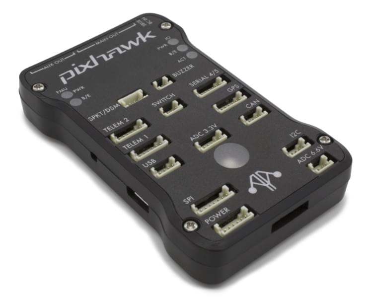
mRo Pixhawk Flight Controller (Pixhawk 1)
WARNING
PX4 does not manufacture this (or any) autopilot. Contact the manufacturer for hardware support or compliance issues.
The mRo Pixhawk® is a hardware compatible version of the original Pixhawk 1. It runs PX4 on the NuttX OS.
TIP
The controller can be used as a drop-in replacement for the 3DR® Pixhawk 1. The main difference is that it is based on the Pixhawk-project FMUv3 open hardware design, which corrects a bug that limited the original Pixhawk 1 to 1MB of flash.
Assembly/setup instructions for use with PX4 are provided here: Pixhawk Wiring Quickstart
TIP
This autopilot is supported by the PX4 maintenance and test teams.
主要特性
微处理器:
- 32-bit STM32F427 Cortex® M4 core with FPU
- 168 MHz/256 KB RAM/2 MB Flash
- 32 bit STM32F100 failsafe co-processor
- 24 MHz/8 KB RAM/64 KB Flash
传感器:
- ST Micro L3GD20 3-axis 16-bit gyroscope
- ST Micro LSM303D 3-axis 14-bit accelerometer / magnetometer
- Invensense® MPU 6000 3-axis accelerometer/gyroscope
- MEAS MS5611 气压计
接口:
- 5x UART (serial ports), one high-power capable, 2x with HW flow control
- 2x CAN
- Spektrum DSM / DSM2 / DSM-X® Satellite compatible input up to DX8 (DX9 and above not supported)
- Futaba® S.BUS compatible input and output
- PPM sum signal
- RSSI (PWM or voltage) input
- I2C
- SPI
- 3.3 and 6.6V ADC inputs
- External microUSB port
电源系统
- Ideal diode controller with automatic failover
- Servo rail high-power (7 V) and high-current ready
- All peripheral outputs over-current protected, all inputs ESD protected
重量和尺寸:
- Weight: 38g (1.31oz)
- Width: 50mm (1.96")
- Thickness: 15.5mm (.613")
- Length: 81.5mm (3.21")
访问链接
- Bare Bones - Just the board (useful as a 3DR Pixhawk replacement)
- mRo Pixhawk 2.4.6 Essential Kit! - Everything except for telemetry radios
- mRo Pixhawk 2.4.6 Cool Kit! (Limited edition) - Everything you need including telemetry radios
编译固件
TIP
Most users will not need to build this firmware! It is pre-built and automatically installed by QGroundControl when appropriate hardware is connected.
To build PX4 for this target:
make px4_fmu-v3_defaultDebug Ports
Console Port
The PX4 System Console runs on the port labeled SERIAL4/5.
TIP
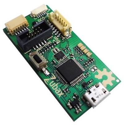
A convenient way to connect to the console is to use a Zubax BugFace BF1, as it comes with connectors that can be used with several different Pixhawk devices. Simply connect the 6-pos DF13 1:1 cable on the Zubax BugFace BF1 to the Pixhawk SERIAL4/5 port.
The pinout is standard serial pinout, designed to connect to a 3.3V FTDI cable (5V tolerant).
| 3DR Pixhawk 1 | FTDI | ||
|---|---|---|---|
| 1 | + 5v (红色) | N/C | |
| 2 | S4 Tx | N/C | |
| 3 | S4 Rx | N/C | |
| 4 | S5 Tx | 5 | FTDI RX (黄色) |
| 5 | S5 Rx | 4 | FTDI TX (橙色) |
| 6 | GND | 1 | FTDI GND (黑色) |
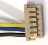
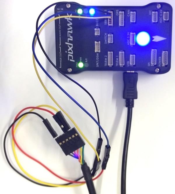
The wiring for an FTDI cable to a 6-pos DF13 1:1 connector is shown in the figure below.
The complete wiring is shown below.
INFO
For information on how to use the console see: System Console.
SWD Port
The SWD (JTAG) ports are hidden under the cover (which must be removed for hardware debugging). There are separate ports for FMU and IO, as highlighted below.
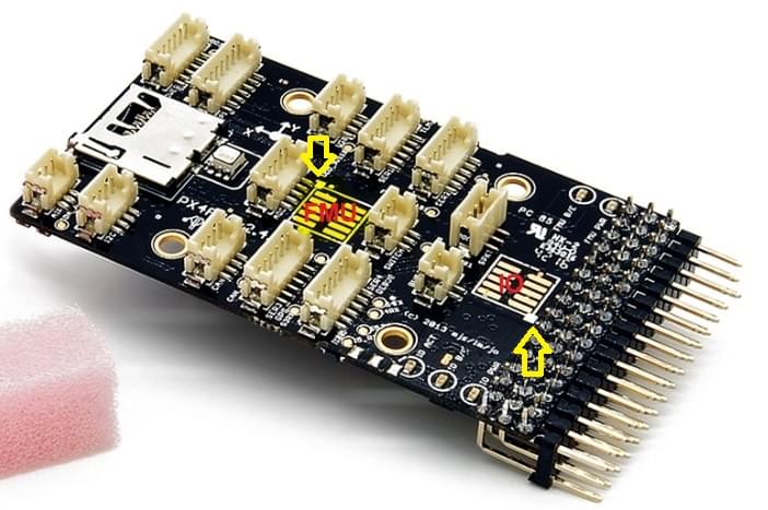
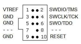
The ports are ARM 10-pin JTAG connectors, which you will probably have to solder. The pinout for the ports is shown below (the square markers in the corners above indicates pin 1).
INFO
All Pixhawk FMUv2 boards have a similar SWD port.
针脚定义
TELEM1,TELEM2 接口
| 针脚 | 信号 | 电压 |
|---|---|---|
| 1(红) | VCC | +5V |
| 2 | TX (OUT) | +3.3V |
| 3 | RX (IN) | +3.3V |
| 4(黑) | CTS (IN) | +3.3V |
| 6 | RTS (OUT) | +3.3V |
| 6 | GND | GND |
GPS 接口
| 针脚 | 信号 | 电压 |
|---|---|---|
| 1(红) | VCC | +5V |
| 2 | TX (OUT) | +3.3V |
| 3 | RX (IN) | +3.3V |
| 4(黑) | CAN2 TX | +3.3V |
| 6 | CAN2 RX | +3.3V |
| 6 | GND | GND |
SERIAL 4/5 port
Due to space constraints two ports are on one connector.
| 针脚 | 信号 | 电压 |
|---|---|---|
| 1(红) | VCC | +5V |
| 2 | TX (#4) | +3.3V |
| 3 | RX (#4) | +3.3V |
| 4(黑) | TX (#5) | +3.3V |
| 6 | RX (#5) | +3.3V |
| 6 | GND | GND |
ADC 6.6V
| 针脚 | 信号 | 电压 |
|---|---|---|
| 1(红) | VCC | +5V |
| 2 | ADC IN | up to +6.6V |
| 3 | GND | GND |
ADC 3.3V
| 针脚 | 信号 | 电压 |
|---|---|---|
| 1(红) | VCC | +5V |
| 2 | ADC IN | up to +3.3V |
| 3 | GND | GND |
| 4(黑) | ADC IN | up to +3.3V |
| 6 | GND | GND |
I2C
| 针脚 | 信号 | 电压 |
|---|---|---|
| 1(红) | VCC | +5V |
| 2 | SCL | +3.3 (pullups) |
| 3 | SDA | +3.3 (pullups) |
| 4(黑) | GND | GND |
CAN
| 针脚 | 信号 | 电压 |
|---|---|---|
| 1(红) | VCC | +5V |
| 2 | CAN_H | +12V |
| 3 | CAN_L | +12V |
| 4(黑) | GND | GND |
SPI
| 针脚 | 信号 | 电压 |
|---|---|---|
| 1(红) | VCC | +5V |
| 2 | SPI_EXT_SCK | +3.3 |
| 3 | SPI_EXT_MISO | +3.3 |
| 4(黑) | SPI_EXT_MOSI | +3.3 |
| 6 | !SPI_EXT_NSS | +3.3 |
| 6 | !GPIO_EXT | +3.3 |
| 7 | GND | GND |
POWER
| 针脚 | 信号 | 电压 |
|---|---|---|
| 1(红) | VCC | +5V |
| 2 | VCC | +5V |
| 3 | 电流 | +3.3V |
| 4(黑) | 电压 | +3.3V |
| 6 | GND | GND |
| 6 | GND | GND |
SWITCH
| 针脚 | 信号 | 电压 |
|---|---|---|
| 1(红) | VCC | +3.3V |
| 2 | !IO_LED_SAFETY | GND |
| 3 | SAFETY | GND |
串口映射
| UART | 设备 | Port |
|---|---|---|
| UART1 | /dev/ttyS0 | IO debug |
| USART2 | /dev/ttyS1 | TELEM1 (流控) |
| USART3 | /dev/ttyS2 | TELEM2 (流控) |
| UART4 | ||
| UART7 | CONSOLE | |
| UART8 | SERIAL4 |
串口映射
| UART | 设备 | Port |
|---|---|---|
| UART1 | /dev/ttyS0 | IO debug |
| USART2 | /dev/ttyS1 | TELEM1 (流控) |
| USART3 | /dev/ttyS2 | TELEM2 (流控) |
| UART4 | ||
| UART7 | CONSOLE | |
| UART8 | SERIAL4 |
原理图
The board is based on the Pixhawk-project FMUv3 open hardware design.
- FMUv3 schematic -- Schematic and layout
INFO
As a CC-BY-SA 3.0 licensed Open Hardware design, all schematics and design files are available.