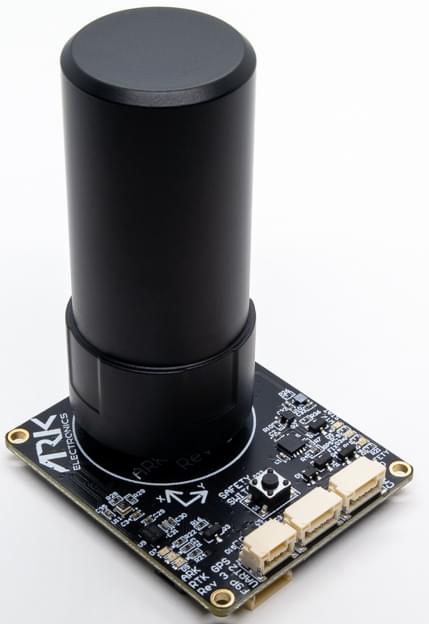
ARK RTK GPS
ARK RTK GPS is an open source DroneCAN RTK GPS, u-blox F9P, magnetometer, barometer, IMU, buzzer, and safety switch module.
购买渠道
Order this module from:
- ARK Electronics (US)
Hardware Specifications
- Open Source Schematic and BOM
- 传感器
- Ublox F9P GPS
- Multi-band GNSS receiver delivers centimetre level accuracy in seconds
- Concurrent reception of GPS, GLONASS, Galileo and BeiDou
- Multi-band RTK with fast convergence times and reliable performance
- High update rate for highly dynamic applications
- Centimetre accuracy in a small and energy efficient module
- Moving Base for Heading
- Bosch BMM150 Magnetometer
- Bosch BMP388 Barometer
- Invensense ICM-42688-P 6-Axis IMU
- Ublox F9P GPS
- STM32F412CEU6 MCU
- Safety Button
- 蜂鸣器
- Two Pixhawk Standard CAN Connectors (4 Pin JST GH)
- F9P
UART 2Connector- 3 Pin JST GH
- TX, RX, GND
- Pixhawk Standard Debug Connector (6 Pin JST SH)
- LED Indicators
- Safety LED
- GPS Fix
- RTK Status
- RGB system status
- USA Built
- Power Requirements
- 5V
- 170mA Average
- 180mA Max
硬件安装
布线
The ARK RTK GPS is connected to the CAN bus using a Pixhawk standard 4 pin JST GH cable. For more information, refer to the CAN Wiring instructions.
Mounting
The recommended mounting orientation is with the connectors on the board pointing towards the back of vehicle.
The sensor can be mounted anywhere on the frame, but you will need to specify its position, relative to vehicle centre of gravity, during PX4 configuration.
Firmware Setup
ARK RTK GPS runs the PX4 cannode firmware. As such, it supports firmware update over the CAN bus and dynamic node allocation.
ARK RTK GPS boards ship with recent firmware pre-installed, but if you want to build and flash the latest firmware yourself, refer to the cannode firmware build instructions.
Firmware target: ark_can-rtk-gps_default Bootloader target: ark_can-rtk-gps_canbootloader
Flight Controller Setup
Enabling DroneCAN
In order to use the ARK RTK GPS, connect it to the Pixhawk CAN bus and enable the DroneCAN driver by setting parameter UAVCAN_ENABLE to 2 for dynamic node allocation (or 3 if using DroneCAN ESCs).
步骤如下:
- In QGroundControl set the parameter UAVCAN_ENABLE to
2or3and reboot (see Finding/Updating Parameters). - Connect ARK RTK GPS CAN to the Pixhawk CAN.
Once enabled, the module will be detected on boot. GPS data should arrive at 10Hz.
PX4 配置
You need to set necessary DroneCAN parameters and define offsets if the sensor is not centred within the vehicle:
- Enable GPS yaw fusion by setting bit 3 of EKF2_GPS_CTRL to true.
- Enable GPS blending to ensure the heading is always published by setting SENS_GPS_MASK to 7 (all three bits checked).
- If using Moving Baseline & GPS Heading, set SENS_GPS_PRIME to the CAN node ID of the Moving Base module. The moving base is preferred because the rover receiver in a moving baseline configuration can experience degraded navigation rate and increased data latency when corrections are intermittent.
- Enable UAVCAN_SUB_GPS, UAVCAN_SUB_MAG, and UAVCAN_SUB_BARO.
- The parameters SENS_GPS0_OFFX, SENS_GPS0_OFFY and SENS_GPS0_OFFZ can be set to account for the offset of the ARK RTK GPS from the vehicles centre of gravity.
ARK RTK GPS Configuration
You may need to configure the following parameters on the ARK RTK GPS itself:
| Parameter | 描述 |
|---|---|
| CANNODE_NODE_ID | CAN node ID (0 for dynamic allocation). If set to 0 (default), dynamic node allocation is used. Set to 1-125 to use a static node ID. |
| CANNODE_TERM | CAN built-in bus termination. Set to 1 if this is the last node on the CAN bus. |
Setting Up Rover and Fixed Base
Position of the rover is established using RTCM messages from the RTK base module (the base module is connected to QGC, which sends the RTCM information to PX4 via MAVLink).
PX4 DroneCAN parameters:
- UAVCAN_PUB_RTCM:
- Makes PX4 publish RTCM messages (RTCMStream) to the bus (which it gets from the RTK base module via QGC).
Rover module parameters (also set using QGC):
- CANNODE_SUB_RTCM tells the rover that it should subscribe to RTCMStream RTCM messages on the bus (from the moving base).
INFO
Use UAVCAN_PUB_MBD and CANNODE_SUB_MBD instead if you want to implement moving base (see below) at the same time.
For more information see Rover and Fixed Base in the DroneCAN guide.
Setting Up Moving Baseline & GPS Heading
The simplest way to set up moving baseline and GPS heading with two ARK RTK GPS modules is via CAN, though it can be done via UART to reduce traffic on the CAN bus if desired.
Note that a heading is only output if the Rover is in RTX Fixed mode. It will not output a heading in RTK Float.
Setup via CAN:
- Ensure the ARK RTK GPS modules are connected to the Pixhawk via CAN (one can connect to another's secondary CAN port). The two ARK RTK GPS must be connected to the same CAN bus for corrections to be sent.
- Choose one ARK RTK GPS to be the Rover and one to be the Moving Base.
- Reopen QGroundControl, go to parameters, and select
Standardto hide that dropdown and selectComponent ##to view each of your ARK RTK GPS's CAN node parametersINFO
Component ##won't be visible unless the ARK RTK GPS is connected to the Pixhawk prior to opening QGroundControl.
:::
- On the Rover, set the following:
- GPS_UBX_MODE to
3 - GPS_YAW_OFFSET to
0if your Rover is in front of your Moving Base,90if Rover is right of Moving Base,180if Rover is behind Moving Base, or270if Rover is left of Moving Base. - CANNODE_SUB_MBD to
1.
- GPS_UBX_MODE to
- On the Moving Base, set the following:
- GPS_UBX_MODE to
4. - CANNODE_PUB_MBD to
1.
- GPS_UBX_MODE to
- On the Flight Controller, set SENS_GPS_PRIME to the CAN node ID of the Moving Base (see PX4 Configuration).
Setup via UART:
- Ensure the ARK RTK GPS modules are connected to the Pixhawk via CAN.
- Ensure the ARK RTK GPS modules are connected to each other via their UART2 port (UART2 pinout shown below). Note that TX of one module needs to connect with RX of the other.
| 针脚 | 参数名 |
|---|---|
| 1 | TX |
| 2 | RX |
| 3 | GND |
- On the Rover, set the following:
- GPS_UBX_MODE to
1 - GPS_YAW_OFFSET to
0if your Rover is in front of your Moving Base,90if Rover is right of Moving Base,180if Rover is behind Moving Base, or270if Rover is left of Moving Base.
- GPS_UBX_MODE to
- On the Moving Base, set the following:
- GPS_UBX_MODE to
2.
- GPS_UBX_MODE to
- On the Flight Controller, set SENS_GPS_PRIME to the CAN node ID of the Moving Base (see PX4 Configuration).
For more information see Rover and Moving Base in the DroneCAN guide.
LED含义
The GPS status lights are located to the right of the connectors
- Blinking green is GPS fix
- Blinking blue is received corrections and RTK Float
- Solid blue is RTK Fixed
The CAN status lights are located top the left of the connectors
- Slow blinking green is waiting for CAN connection
- Fast blinking green is normal operation
- Slow blinking green and blue is CAN enumeration
- Fast blinking blue and red is firmware update in progress
- Blinking red is error
- If you see a red LED there is an error and you should check the following
- Make sure the flight controller has an SD card installed
- Make sure the ARK RTK GPS has
ark_can-rtk-gps_canbootloaderinstalled prior to flashingark_can-rtk-gps_default - Remove binaries from the root and ufw directories of the SD card and try to build and flash again
- If you see a red LED there is an error and you should check the following
Updating Ublox F9P Module
ARK RTK GPS comes with the Ublox F9P module up to date with version 1.13 or newer. However, you can check the version and update the firmware if desired.
步骤如下:
- Download u-center from u-blox.com and install on your PC (Windows only)
- Open the u-blox ZED-F9P website
- Scroll down and click on the "Show Legacy Documents" box
- Scroll down again to Firmware Update and download your desired firmware (at least version 1.13 is needed)
- While holding down the safety switch on the ARK RTK GPS, connect it to power via one of its CAN ports and hold until all 3 LEDs blink rapidly
- Connect the ARK RTK GPS to your PC via its debug port with a cable such as the Black Magic Probe or an FTDI
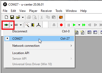
- Open u-center, select the COM port for the ARK RTK GPS and connect
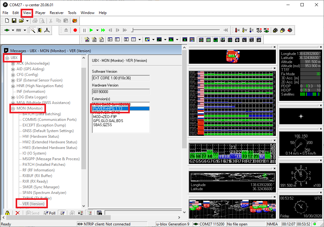
- Check the current firmware version by selecting View, Messages View, UBX, MON, VER
- To update the firmware:
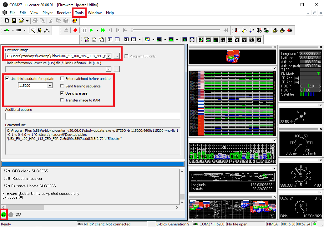
- Select Tools, Firmware Update
- The Firmware image field should be the .bin file downloaded from the u-blox ZED-F9P website
- Check the "Use this baudrate for update" checkbox and select 115200 from the drop-down
- Ensure the other checkboxes are as shown below
- Push the green GO button on the bottom left
- "Firmware Update SUCCESS" should be displayed if it updated successfully
另见
- ARK RTK GPS Documentation (ARK Docs)