mRo Pixracer
WARNING
PX4 does not manufacture this (or any) autopilot. Contact the manufacturer for hardware support or compliance issues.
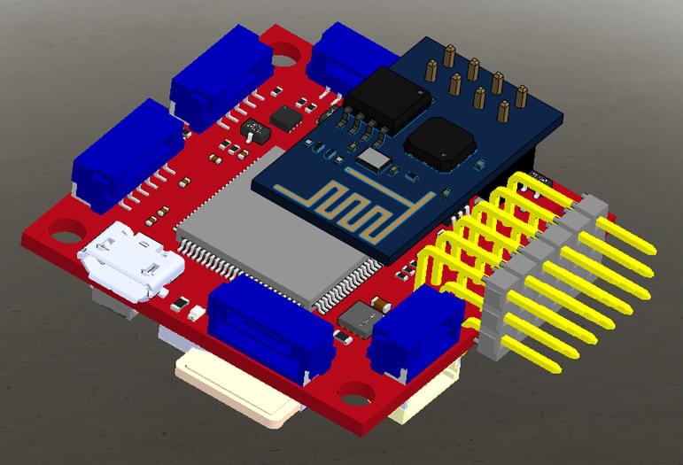
The Pixhawk® XRacer board family is optimized for small racing quads and planes. In contrast to Pixfalcon and Pixhawk it has in-built WiFi, new sensors, convenient full servo headers, CAN and supports 2M flash.

TIP
This autopilot is supported by the PX4 maintenance and test teams.
主要特性
- Main System-on-Chip: STM32F427VIT6 rev.3
- CPU: 180 MHz ARM Cortex® M4 with single-precision FPU
- RAM: 256 KB SRAM (L1)
- Standard FPV form factor: 36x36 mm with standard 30.5 mm hole pattern
- Invensense® ICM-20608 Accel / Gyro (4 KHz) / MPU9250 Accel / Gyro / Mag (4 KHz)
- HMC5983 magnetometer with temperature compensation
- Measurement Specialties MS5611 barometer
- JST GH connectors
- microSD (logging)
- Futaba S.BUS and S.BUS2 / Spektrum DSM2 and DSMX / Graupner SUMD / PPM input / Yuneec ST24
- FrSky® telemetry port
- OneShot PWM out (configurable)
- Optional: Safety switch and buzzer
Where to Buy
Pixracer Pro is available from the store.3dr.com.
Accessories include:
- Digital airspeed sensor
- Hobbyking® OSD + EU Telemetry (433 MHz) (Discontinued)
Kit
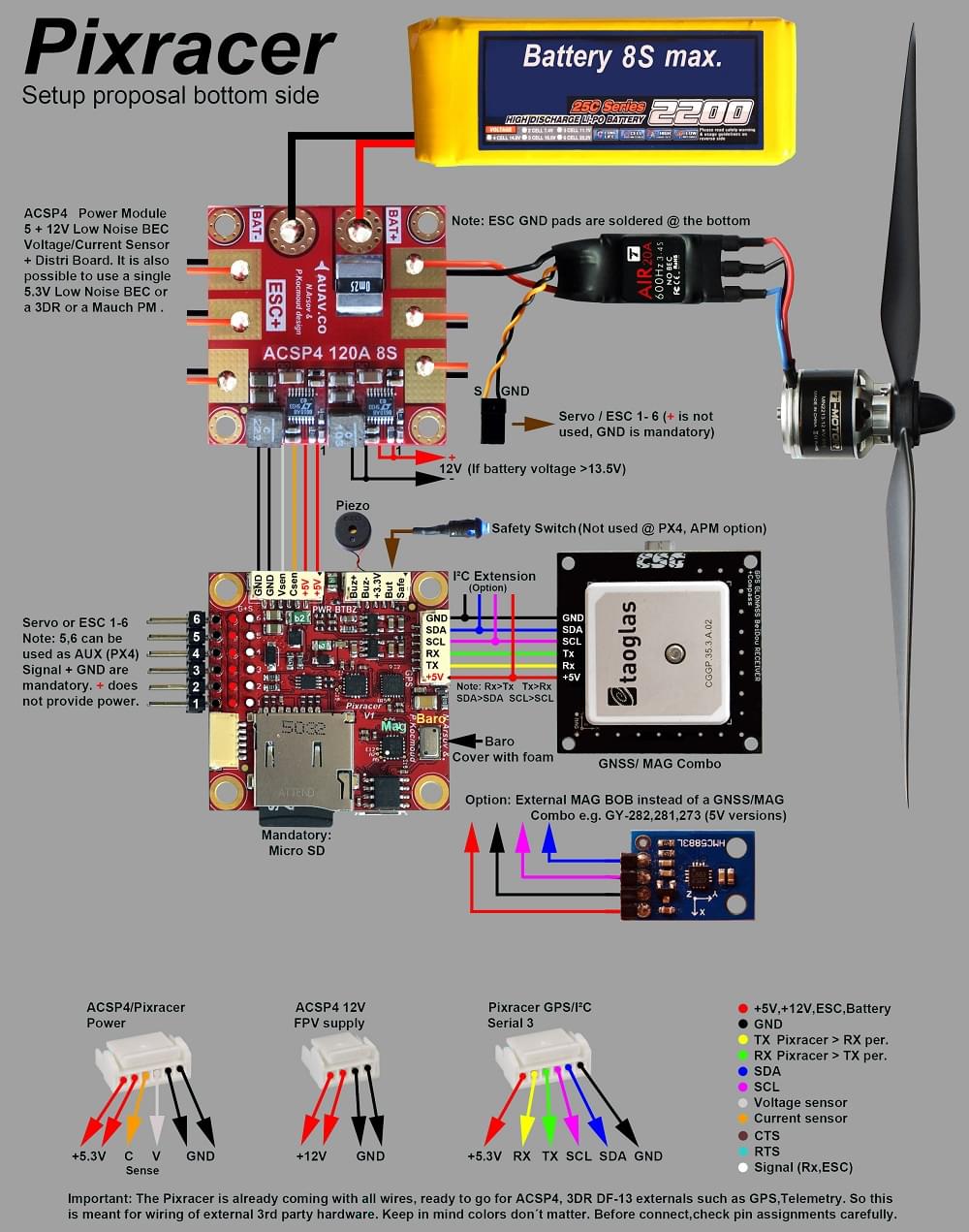
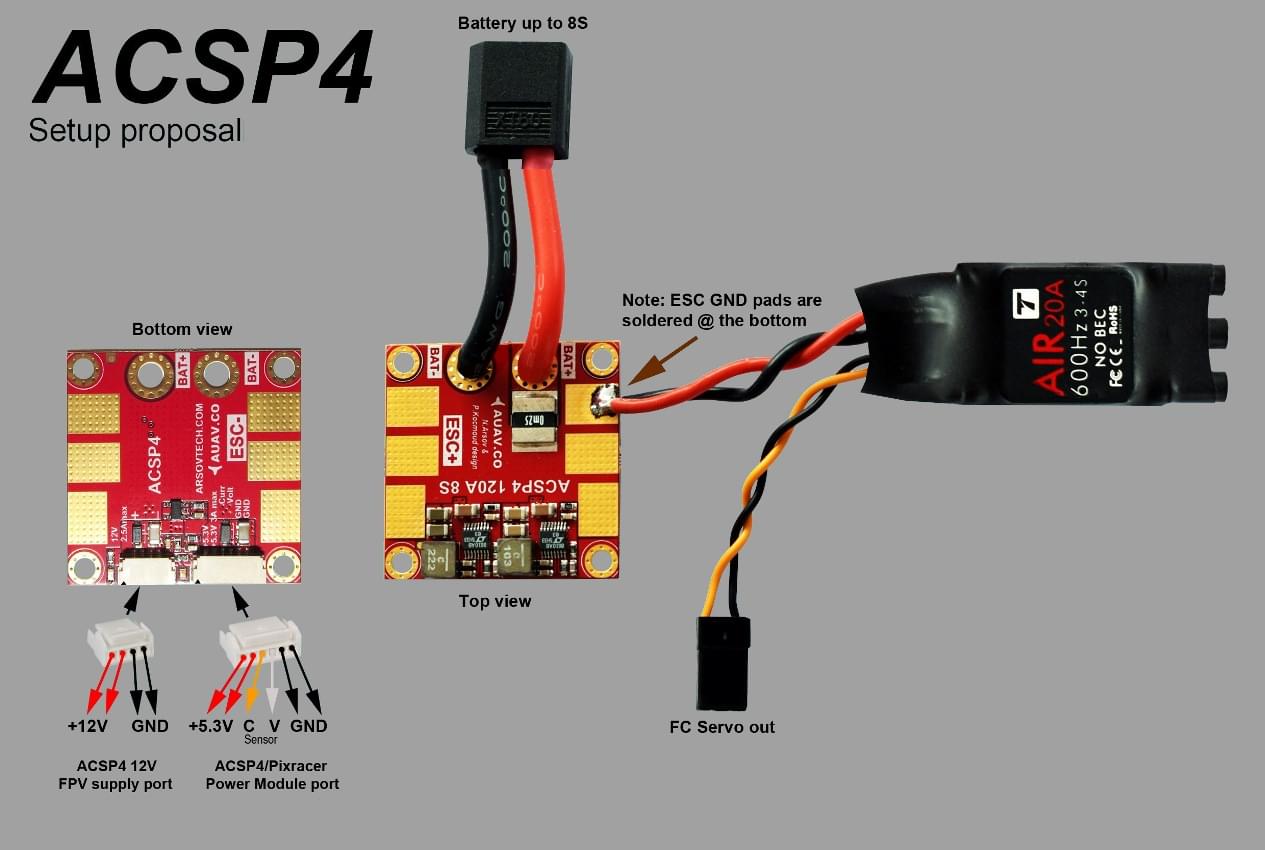
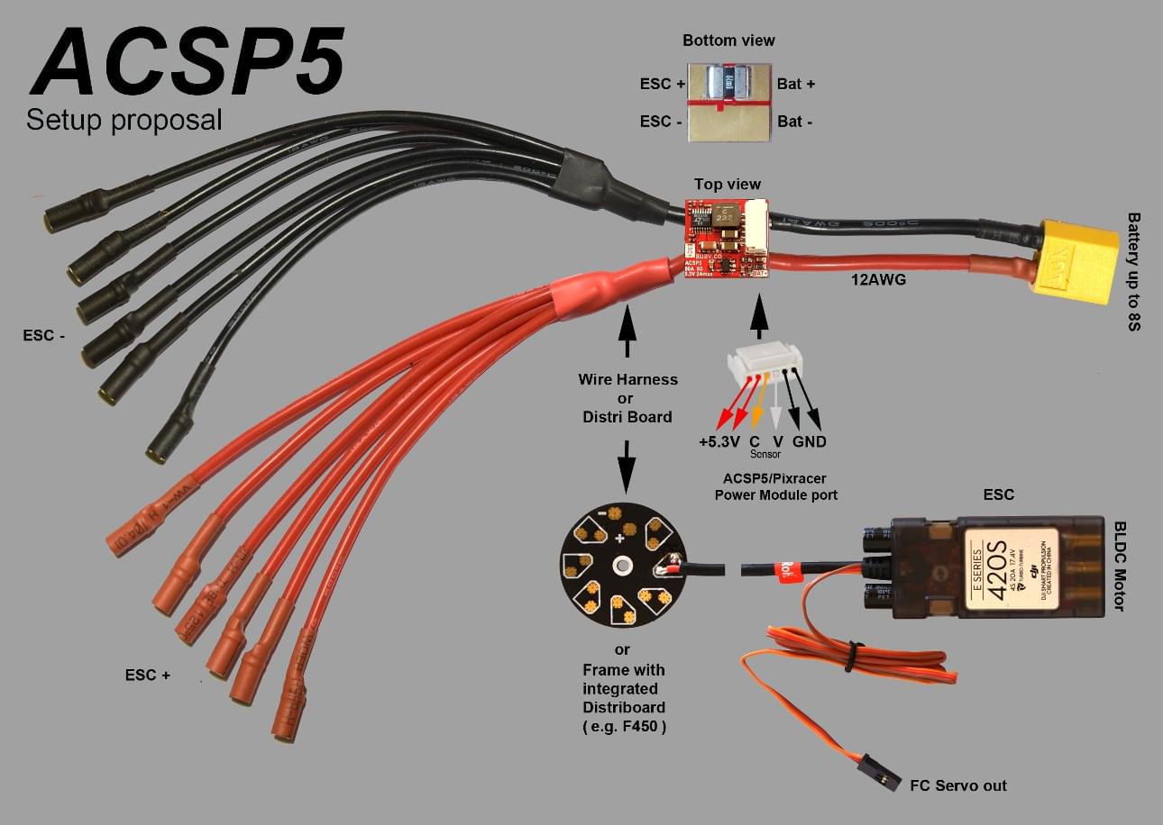
The Pixracer is designed to use a separate avionics power supply. This is necessary to avoid current surges from motors or ESCs to flow back to the flight controller and disturb its delicate sensors.
- Power module (with voltage and current sensing)
- I2C splitter (supporting AUAV, Hobbyking and 3DR® peripherals)
- Cable kit for all common peripherals
Wifi (no USB required)
One of the main features of the board is its ability to use Wifi for flashing new firmware, system setup and in-flight telemetry. This frees it of the need of any desktop system.
INFO
Firmware upgrade is not yet enabled over WiFi (it is supported by the default bootloader but not yet enabled). Setup and telemetry are supported.
组装
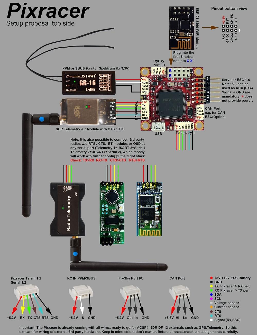
See the Pixracer Wiring Quickstart
Wiring Diagrams
INFO
If using TELEM2 for an external telemetry module you will need to configure it as a MAVLink serial port. For more information see: Pixracer Wiring Quickstart > External Telemetry
连接器
All connectors follow the Pixhawk connector standard. Unless noted otherwise all connectors are JST GH.
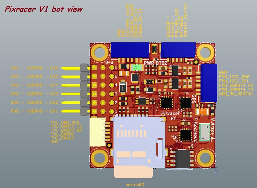
针脚定义
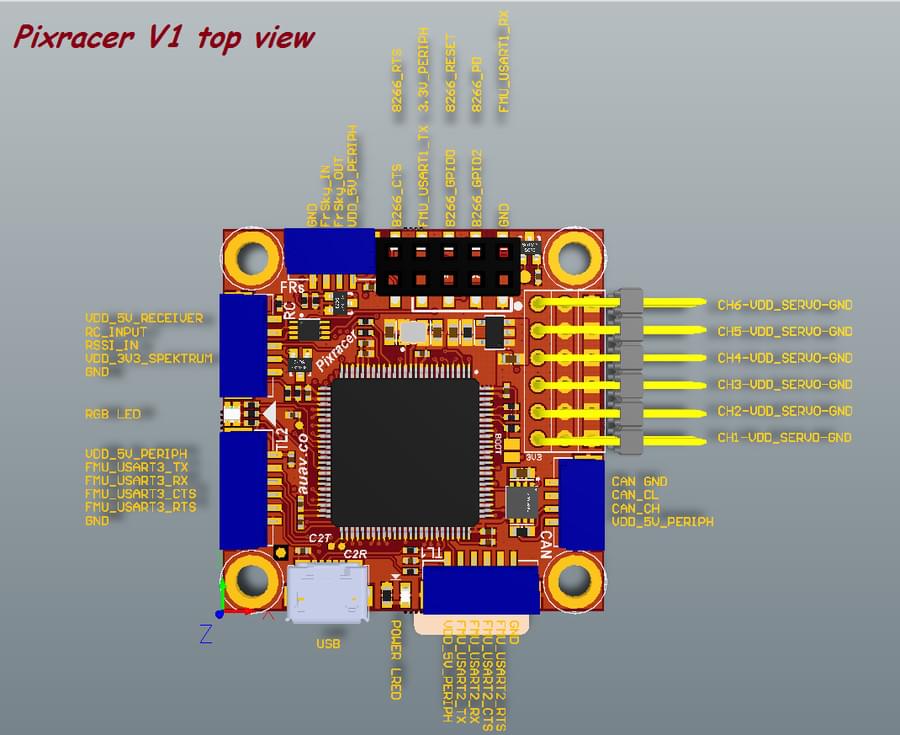
TELEM1, TELEM2+OSD ports
| 针脚 | 信号 | 电压 |
|---|---|---|
| 1(红) | VCC | +5V |
| 2 | TX (OUT) | +3.3V |
| 3 | RX (IN) | +3.3V |
| 4(黑) | CTS (IN) | +3.3V |
| 6 | RTS (OUT) | +3.3V |
| 6 | GND | GND |
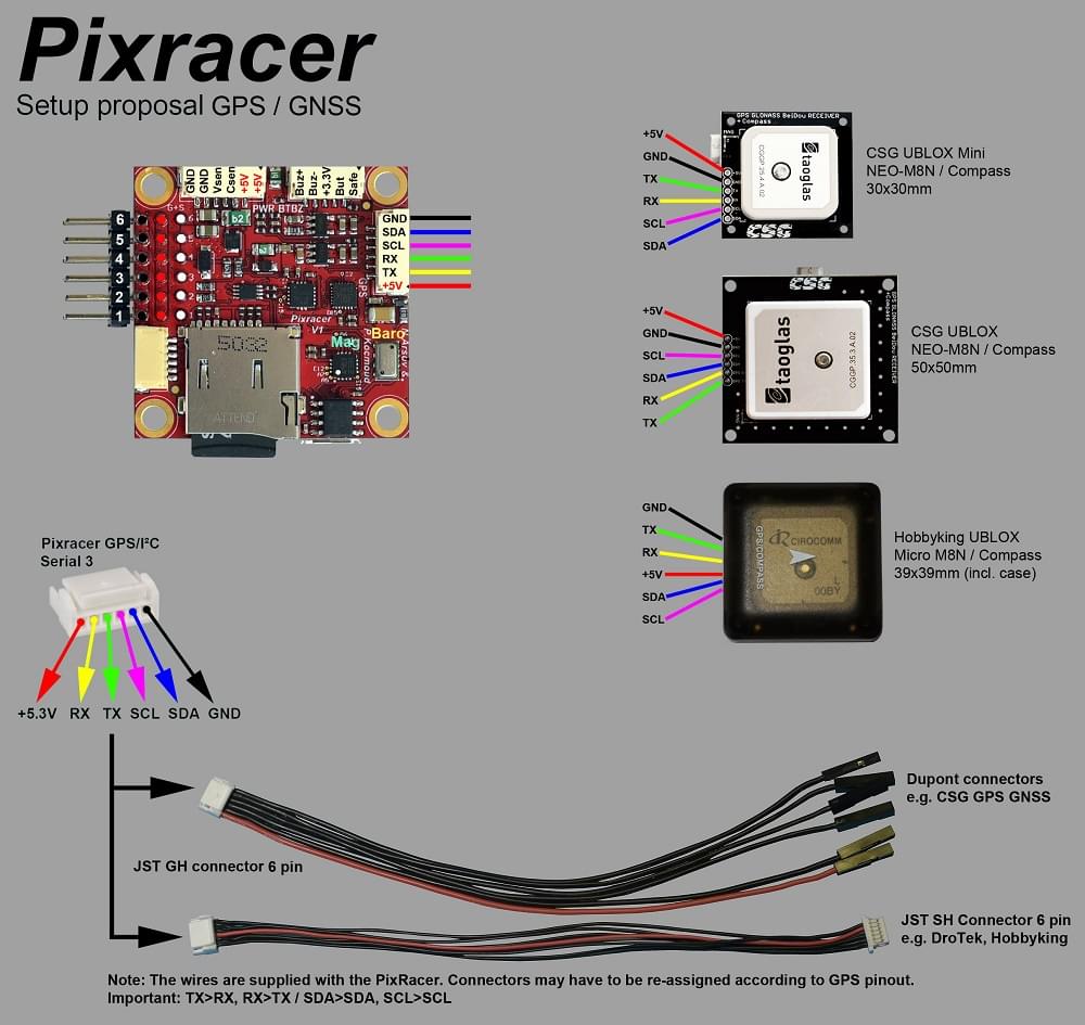
GPS 接口
| 针脚 | 信号 | 电压 |
|---|---|---|
| 1(红) | VCC | +5V |
| 2 | TX (OUT) | +3.3V |
| 3 | RX (IN) | +3.3V |
| 4(黑) | I2C1 SCL | +3.3V |
| 6 | I2C1 SDA | +3.3V |
| 6 | GND | GND |
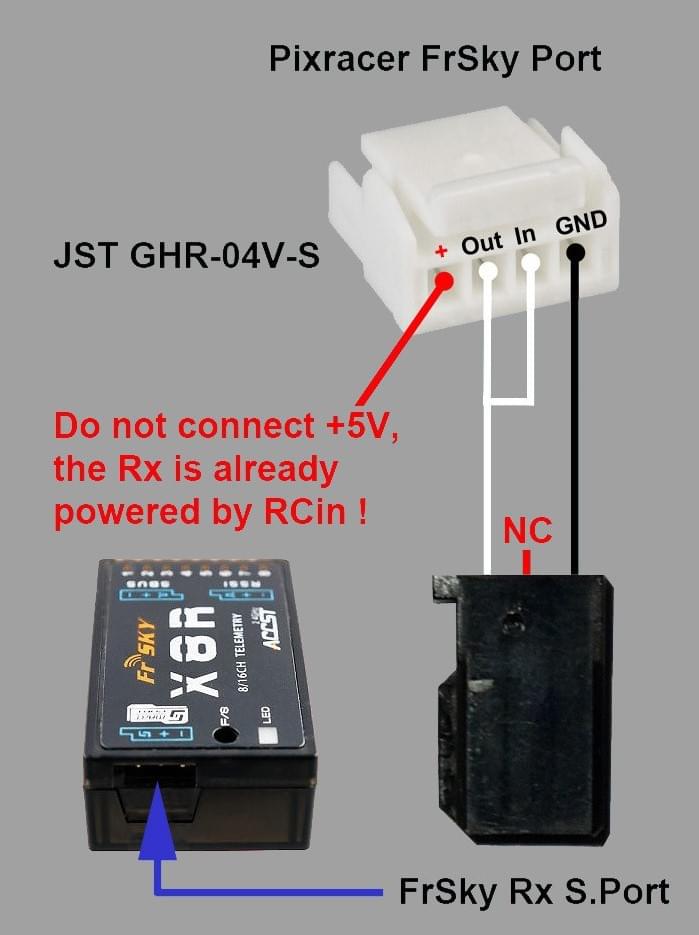
FrSky Telemetry / SERIAL4
| 针脚 | 信号 | 电压 |
|---|---|---|
| 1(红) | VCC | +5V |
| 2 | TX (OUT) | +3.3V |
| 3 | RX (IN) | +3.3V |
| 4(黑) | GND | GND |
RC Input (accepts PPM / S.BUS / Spektrum / SUMD / ST24)
| 针脚 | 信号 | 电压 |
|---|---|---|
| 1(红) | VCC | +5V |
| 2 | RC IN | +3.3V |
| 3 | RSSI IN | +3.3V |
| 4(黑) | VDD 3V3 | +3.3V |
| 6 | GND | GND |
CAN
| 针脚 | 信号 | 电压 |
|---|---|---|
| 1(红) | VCC | +5V |
| 2 | CAN_H | +12V |
| 3 | CAN_L | +12V |
| 4(黑) | GND | GND |
POWER
| 针脚 | 信号 | 电压 |
|---|---|---|
| 1(红) | VCC | +5V |
| 2 | VCC | +5V |
| 3 | 电流 | +3.3V |
| 4(黑) | 电压 | +3.3V |
| 6 | GND | GND |
| 6 | GND | GND |
SWITCH
| 针脚 | 信号 | 电压 |
|---|---|---|
| 1(红) | SAFETY | GND |
| 2 | !IO_LED_SAFETY | GND |
| 3 | VCC | +3.3V |
| 4(黑) | BUZZER- | - |
| 6 | BUZZER+ | - |
调试接口
The pinouts and connector comply with the Pixhawk Debug Mini interface defined in the Pixhawk Connector Standard (JST SM06B connector).
| 针脚 | 信号 | 电压 |
|---|---|---|
| 1(红) | VCC TARGET SHIFT | +3.3V |
| 2 | UART7 Tx | +3.3V |
| 3 | UART7 Rx | +3.3V |
| 4(黑) | SWDIO | +3.3V |
| 6 | SWCLK | +3.3V |
| 6 | GND | GND |
For information about using this port see:
- SWD Debug Port
- PX4 System Console (Note, the FMU console maps to UART7).
串口映射
| UART | 设备 | Port |
|---|---|---|
| UART1 | /dev/ttyS0 | WiFi (ESP8266) |
| USART2 | /dev/ttyS1 | TELEM1 (流控) |
| USART3 | /dev/ttyS2 | TELEM2 (流控) |
| UART4 | ||
| UART7 | CONSOLE | |
| UART8 | SERIAL4 |
原理图
The reference is provided as: Altium Design Files
The following PDF files are provided for convenience only:
- pixracer-rc12-12-06-2015-1330.pdf
- pixracer-r14.pdf - R14 or RC14 is printed next to the SDCard socket
编译固件
TIP
Most users will not need to build this firmware! It is pre-built and automatically installed by QGroundControl when appropriate hardware is connected.
To build PX4 for this target:
make px4_fmu-v4_default配置
Compass calibration should be done with USB disconnected. This is always recommended, but is necessary on Pixracer because the USB connection produces particularly large levels of magnetic interference.
Configuration is otherwise the same as for other boards.
Credits
This design was created by Nick Arsov and Phillip Kocmoud and architected by Lorenz Meier, David Sidrane and Leonard Hall.