控制分配 (混控)
INFO
Control allocation replaces the legacy mixing approach used in PX4 v1.13 and earlier. For PX4 v1.13 documentation see: Mixing & Actuators, Geometry Files and Adding a New Airframe Configuration.
PX4从核心控制器获取所需的扭矩和推力指令,并将它们转换为控制电机或作动器的驱动指令。
指令间的转换取决于飞行器的物理构型。 例如,给“向右转”需要给出一个扭矩指令:
- 对于每个副翼都有一个舵机的飞机来说,该指令将会控制一个舵机向高处偏转,另一个向低处偏转。
- 多旋翼将会通过改变所有电机的转速来向右偏航。
PX4将这个转换逻辑区分开,这个逻辑被称为从姿态/角速率控制器输出的“混控”。 这样可以确保核心控制器不需要对每个机型构型进行特殊处理,可以大大提高复用性。
此外,PX4还将输出函数映射至指定的硬件输出。 这也意味着任何电机或舵机可以分配给几乎任何物理输出。

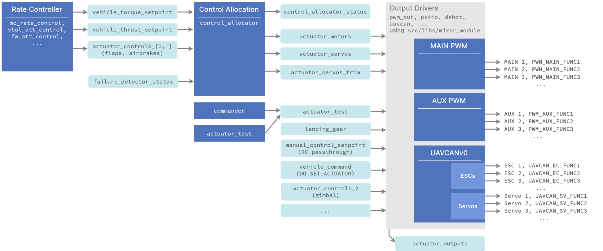
作动器控制流程
模块和uORB话题混控流程概览(点击全屏查看):

备注:
- 角速率控制器输出力矩和推力设定值
- the
control_allocatormodule:- 根据配置参数处理不同飞行器构型
- 进行混控计算
- 处理电机失效
- 发布电机和作动器控制信号
- publishes the servo trims separately so they can be added as an offset when testing actuators (using the test sliders).
- 输出驱动:
- 处理硬件初始化和更新
- use a shared library src/libs/mixer_module. The driver defines a parameter prefix, e.g.
PWM_MAINthat the library then uses for configuration. Its main task is to select from the input topics and assign the right data to the outputs based on the user set<param_prefix>_FUNCxparameter values. For example ifPWM_MAIN_FUNC3is set to Motor 2, the 3rd output is set to the 2nd motor fromactuator_motors. - output functions are defined under src/lib/mixer_module/output_functions.yaml.
- if you want to control an output from MAVLink, set the relevant output function to Offboard Actuator Set x, and then send the MAV_CMD_DO_SET_ACTUATOR MAVLink command.
添加新构型或输出函数
See this commit for how to add a new geometry. The QGC UI will then automatically show the right configuration UI when CA_AIRFRAME is set to the new geometry.
This commit shows how to add a new output function. Any uORB topic can be subscribed and assigned to a function.
Note that parameters for control allocation are defined in src/modules/control_allocator/module.yaml The schema for this file is here (in particular, search for the key mixer:
设置默认机型构型
When adding a new frame configuration, set the appropriate CA_AIRFRAME and other default mixer values for the geometry.
You can see this, for example, in the airframe configuration file 13200_generic_vtol_tailsitter
sh
...
param set-default CA_AIRFRAME 4
param set-default CA_ROTOR_COUNT 2
param set-default CA_ROTOR0_KM -0.05
param set-default CA_ROTOR0_PY 0.2
...
设置构型和输出
The broad geometry and default parameters for a vehicle are set (from the frame configuration file) when selecting the airframe in QGroundControl: Basic Configuration > Airframe.
The geometry parameters and output mapping for the specific frame and flight controller hardware are then configured using the QGroundControl Actuators setup screen: Basic Configuration > Actuator Configuration and Testing.