Hiwonder Ackermann
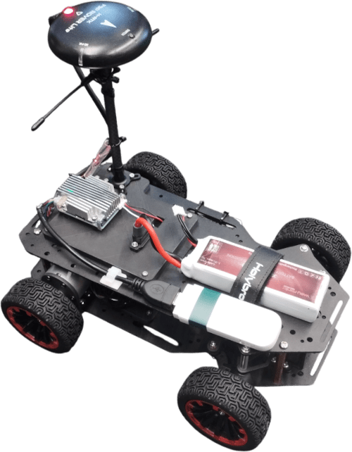
PX4 v1.18The Hiwonder Ackermann rover is a bare-bones platform including a chassis, four wheels, two motors with encoders, a servo and a motor driver board. The chassis offers many mounting points, providing the flexibility to attach your own flight controller, sensors and other payload.
This documentation illustrates the setup of the rover and the configuration of the actuators.
配件列表
TIP
The hardware below is just an example — use whatever you have available. Make sure all parts are compatible with your flight controller's ports, and adjust the wiring as needed. Alternatives are listed in:
The following parts are used in this build:
Frame: Hiwonder Ackermann Chassis
Flight Controller: Auterion Skynode S
INFO
The flight controller and motor driver board used in this build are both directly supplied at the same 3S battery voltage (~11V).
Many flight controllers require a lower voltage power supply, so if you are using a different controller you may need a DC-to-DC converter to power it from the battery — see Power Modules & Power Distribution Boards.
:::
Receiver: TBS Crossfire Nano RX
Power: 3S Lipo Battery
Dc-to-Dc Converter: BEC12S-PRO.
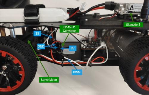
The servo needs to be supplied with 6-8.4V (and with a current rating of higher than 3A). This Dc-to-Dc converted is needed to transform the voltage from the 3S battery to this range.
GNSS: Holybro RTK F9P GPS
I2C Splitter
INFO
This part is only necessary if your flight controller has only one I2C port (we need one for the motor driver board and one for the compass in the GNSS module). Many boards will have a dedicated GPS port (which often includes an I2C port) and one or more separate I2C ports for additional peripherals.
:::
- LTE Dongle: Used to establish a data link between the vehicle and the ground control station.
Wiring and Assembly
The following images shows the wiring of the various components of this build. The connections from the motors to the motor controller board are not shown.
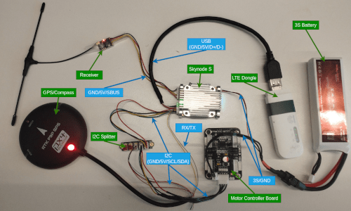
INFO
This image only serves as an example for the wiring process, with your hardware this can look very different. Check the documentation of your parts to ensure that you connect to correct pins.
Now connect the battery to the Dc-to-Dc converter to give it power. To power the servo, connect the red (6-8.4V) and black (GND) wire to the output of the DC-to-Dc converter and the white (PWM) wire to a PWM output of your flight controller.
With the wiring complete, you can now securely attach your hardware to the chassis.
TIP
For the initial build you might attach components using double sided tape. For a longer term solution we highly recommend 3d printing mounts that you attach to the chassis using the mounting points.
Building the Firmware
This frame works with the usual Rover firmware variants on most flight controllers. You can use either prebuilt versions or build the firmware yourself (see Flashing the Rover Build and Building Rover in Rover Configuration/Tuning).
A few boards may omit the hiwonder_emm driver for the Hiwonder 4-Channel Encoder Motor Module used by this vehicle. If your board does not ship with it you will need a custom build — see Hiwonder 4-Channel Encoder Motor Module > Building the Firmware for instructions.
PX4 配置
Use QGroundControl for rover configuration:
- Flash the rover build onto your flight controller with the following adjustments:
- In the Basic Configuration section, select the Airframe tab.
- Choose Hiwonder Ackermann under the Rover category (Alternatively you can set the parameter
SYS_AUTOSTARTto51003).
Then configure the actuators:
Navigate to Actuators Configuration & Testing in QGroundControl.
Select the Hiwonder EMM driver from the list of Actuator Outputs.
Assign the two populated channels of the motor controller board to
Throttle. The channels are noted on the motor controller board (alternatively randomly assign the channels and use the actuator testing tab to find the correct assignments).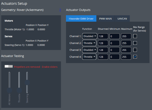
Now ensure that both motors are spinning in the same direction. If that is not the case check the
Rev Rangebox on one of the motors.Arm the rover in Manual Mode and use the trottle stick to drive forwards. If the rover drives backwards instead, invert the
Rev Rangecheckboxes on both motors.To configure the servo motor, assign the populated PWM channel to
Steering. Set the minimum value to800, the maximum to2200and the disarm value to1500.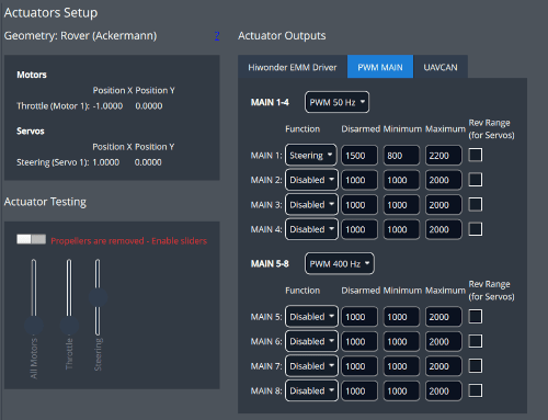
Arm the rover in Manual Mode and use the steering stick to move the servo. If the rover steers in the wrong direction check the
Rev Rangecheckbox of the servo.
You have now successfully setup your rover and can start testing all driving modes PX4 has to offer!