Control Allocation (Mixing)
INFO
Control allocation replaces the legacy mixing approach used in PX4 v1.13 and earlier. For PX4 v1.13 documentation see: Mixing & Actuators, Geometry Files and Adding a New Airframe Configuration.
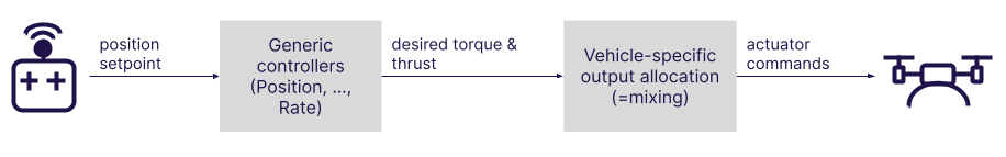
PX4 takes desired torque and thrust commands from the core controllers and translates them to actuator commands which control motors or servos.
The translation depends on the physical geometry of the airframe. For example, given a torque command to "turn right" (say):
- A plane with one servo per aileron will command one of servo high and the other low.
- A multicopter will yaw right by changing the speed of all motors.
PX4 separates this translation logic, which is referred to as "mixing" from the attitude/rate controller. This ensures that the core controllers do not require special handling for each airframe geometry, and greatly improves reusability.
In addition, PX4 abstracts the mapping of output functions to specific hardware outputs. This means that any motor or servo can be assigned to almost any physical output.
Actuator Control Pipeline
Overview of the mixing pipeline in terms of modules and uORB topics (press to show full-screen):
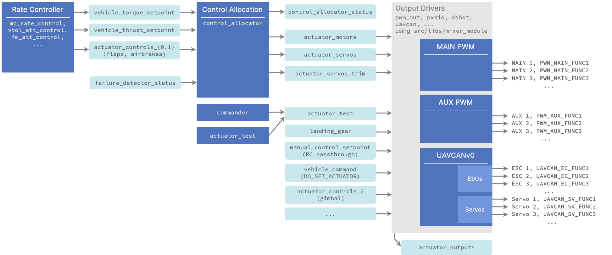
Notes:
- The rate controller outputs torque and thrust setpoints
- the
control_allocatormodule:- handles different geometries based on configuration parameters
- does the mixing
- handles motor failures
- publishes the motor and servo control signals
- publishes the servo trims separately so they can be added as an offset when testing actuators (using the test sliders).
- the output drivers:
- handle the hardware initialization and update
- use a shared library src/libs/mixer_module. The driver defines a parameter prefix, e.g.
PWM_MAINthat the library then uses for configuration. Its main task is to select from the input topics and assign the right data to the outputs based on the user set<param_prefix>_FUNCxparameter values. For example ifPWM_MAIN_FUNC3is set to Motor 2, the 3rd output is set to the 2nd motor fromactuator_motors. - output functions are defined under src/lib/mixer_module/output_functions.yaml.
- if you want to control an output from MAVLink, set the relevant output function to Offboard Actuator Set x, and then send the MAV_CMD_DO_SET_ACTUATOR MAVLink command.
Adding a new Geometry or Output Function
See this commit for how to add a new geometry. The QGC UI will then automatically show the right configuration UI when CA_AIRFRAME is set to the new geometry.
This commit shows how to add a new output function. Any uORB topic can be subscribed and assigned to a function.
Note that parameters for control allocation are defined in src/modules/control_allocator/module.yaml The schema for this file is here (in particular, search for the key mixer:
Setting the Default Frame Geometry
When adding a new frame configuration, set the appropriate CA_AIRFRAME and other default mixer values for the geometry.
You can see this, for example, in the airframe configuration file 13200_generic_vtol_tailsitter
...
param set-default CA_AIRFRAME 4
param set-default CA_ROTOR_COUNT 2
param set-default CA_ROTOR0_KM -0.05
param set-default CA_ROTOR0_PY 0.2
...
Setting up Geometry and Outputs
The broad geometry and default parameters for a vehicle are set (from the frame configuration file) when selecting the airframe in QGroundControl: Basic Configuration > Airframe.
The geometry parameters and output mapping for the specific frame and flight controller hardware are then configured using the QGroundControl Actuators setup screen: Basic Configuration > Actuator Configuration and Testing.