Pixhawk 3 Pro (Discontinued)
WARNING
PX4 does not manufacture this (or any) autopilot. Contact the manufacturer for hardware support or compliance issues.
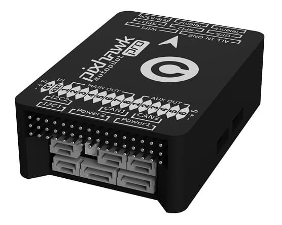
The Pixhawk® 3 Pro is based on the FMUv4 hardware design (Pixracer) with some upgrades and additional features. The board was designed by Drotek® and PX4.

INFO
The main hardware documentation is here: https://drotek.gitbook.io/pixhawk-3-pro/hardware
TIP
This autopilot is supported by the PX4 maintenance and test teams.
总览
- Microcontroller: STM32F469; Flash size is 2MiB, RAM size is 384KiB
- ICM-20608-G gyro / accelerometer
- MPU-9250 gyro / accelerometer / magnetometer
- LIS3MDL compass
- Sensors connected via two SPI buses (one high rate and one low-noise bus)
- Two I2C buses
- Two CAN buses
- Voltage / battery readings from two power modules
- FrSky® Inverter
- 8 Main + 6 AUX PWM outputs (Separate IO chip, PX4IO)
- microSD (logging)
- S.BUS / Spektrum / SUMD / PPM input
- JST GH user-friendly connectors: same connectors and pinouts as Pixracer
Where to buy
No longer available.
编译固件
TIP
Most users will not need to build this firmware! It is pre-built and automatically installed by QGroundControl when appropriate hardware is connected.
To build PX4 for this target:
make px4_fmu-v4pro_default调试接口
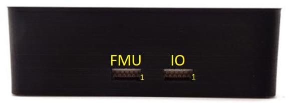
The board has FMU and IO debug ports as shown below.

The pinouts and connector comply with the Pixhawk Debug Mini interface defined in the Pixhawk Connector Standard (JST SM06B connector).
| 针脚 | 信号 | 电压 |
|---|---|---|
| 1(红) | VCC TARGET SHIFT | +3.3V |
| 2 | UART7 Tx | +3.3V |
| 3 | UART7 Rx | +3.3V |
| 4(黑) | SWDIO | +3.3V |
| 6 | SWCLK | +3.3V |
| 6 | GND | GND |
For information about wiring and using this port see:
- SWD Debug Port
- PX4 System Console (Note, the FMU console maps to UART7).
串口映射
| UART | 设备 | Port |
|---|---|---|
| UART1 | /dev/ttyS0 | WiFi |
| USART2 | /dev/ttyS1 | TELEM1 (流控) |
| USART3 | /dev/ttyS2 | TELEM2 (流控) |
| UART4 | ||
| UART7 | CONSOLE | |
| UART8 | SERIAL4 |