단종 : Falcon Vertigo Hybrid VTOL RTF (Dropix)
WARNING
Discontinued The Falcon Venturi FPV Wing frame on which this vehicle is based is no longer available. The Dropix FC used by this vehicle is discontinued.
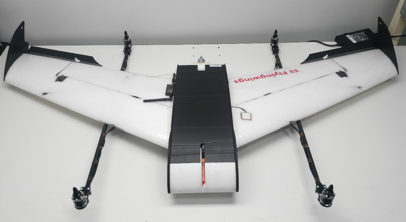
The Falcon Vertigo Hybrid VTOL is a quadplane VTOL aircraft that has been designed to work with PX4 and the Dropix (Pixhawk compatible) flight controller. 소형 GoPro 카메라를 장착할 수 있습니다.
RTF 키트에는 RC 수신기와 텔레메트리를 제외하고, 시스템에 필요한 부품들이 포함되어 있습니다. 부품들을 별도로 구매할 수 있습니다.
주요 정보:
- Frame: Falcon Vertigo Hybrid VTOL
- Flight controller: Dropix (Discontineud)
- Wing span: 1.3m
부품 명세서
필요한 대부분의 부품들이 RTF 키트에 포함되어 있습니다. 부품을 별도 구매하는 경우에는, 아래 부품 목록의 링크를 참고하십시오.
- 사전 적층 EPP 날개
- 윙팁 및 전체 하드웨어
- Dropix flight controller (discontinued) with
- GPS u-blox M8N
- 전원 센서:
- Airspeed Sensor
- Quad power set Tiger Motor MT-2216-11 900kv V2 (discontinued)
- 4 x 프로펠러 10”x 5”(쿼드 모터)
- 4 x ESC 25A
- 프로펠러 10”x 5”1 개 (푸셔 모터)
- 1 x ESC 30A
- 푸셔 모터 전원 시스템
- 탄소 섬유 튜브 및 마운트
- G10 모터 마운트
- 1 x 3700mah 4S 30C Lipo battery
- Dropix power distribution board and cable
이 키트는 라디오 수신기 또는 텔레메트리(선택 사항)는 제공하지 않습니다. 다음의 부품을 사용하여 조립하였습니다.
- Receiver: FrSSKY D4R-II
- Telemetry: Holybro 100mW 915MHz modules (Discontinued)
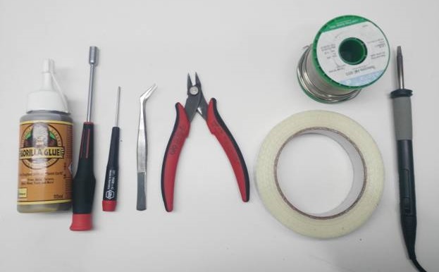
필요한 공구들
아래의 도구들을 사용하여 기체를 조립하였습니다.
- 필립스 스크류드라이버
- 5.5 mm 육각 스크류드라이버
- 전선 커터
- 납땜 인두 및 땜납
- 취미 스테인리스 핀셋
- 고릴라 접착제
- 유리 섬유 강화 테이프
조립 단계
RTF 키트는 아래와 같이 조립하여야 합니다.
1 단계 : 모터 마운트 부착
그림과 같이 윙 브래킷 내부에 고릴라 접착제를 펴서 바릅니다.
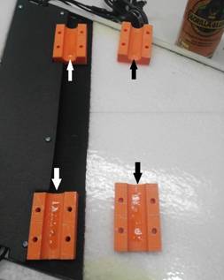
브래킷에 카본 튜브를 부착합니다. 브래킷과 튜브는 흰색 표시를 사용하여 정렬합니다 (그림 참조).
INFO
This is very important because the white mark indicates the center of gravity.
:::

다음 이미지는 다른 관점에서 막대들의 정렬을 보여줍니다.
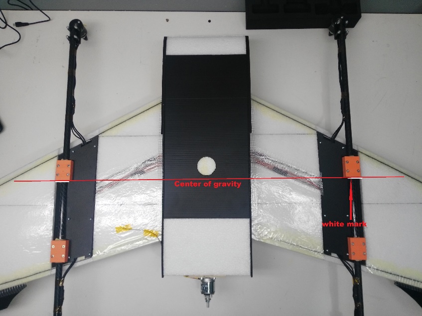
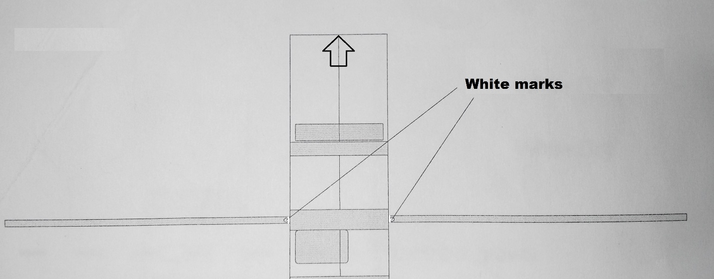
2 단계 : 날개 부착
두 탄소 튜브를 동체에 삽입합니다.

각 튜브에있는 두 개의 흰색 표시 사이에 고릴라 접착제를 바릅니다 (빨간색 화살표로 표시됨). 중앙의 흰색 표시 (파란색 화살표)는 동체 중앙에 배치되고, 다른 표시는 측면에 배치됩니다.

탄소 튜브가 동체 내부에 있으면, 튜브의 나머지 부분에 고릴라 접착제를 바르고 날개를 부착하십시오.
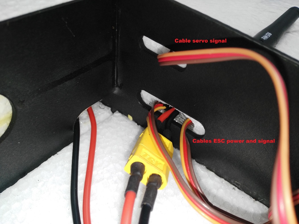
동체에는 모터와 서보 케이블을 위한 두 개의 구멍이 있습니다. 구멍으로 케이블을 통과시킨 다음 날개를 동체에 연결합니다.

동체 내에 제공된 커넥터를 사용하여 방금 날개에서 ESC로 통과한 신호 케이블을 연결합니다. ESC는 이미 모터에 연결되어 있으며, 올바른 순서로 회전하도록 설정되어 있습니다 (나중 단계에서 ESC PDB를 전원 모듈에 연결해야 함).

ESC와 마찬가지로 서보는 이미 설치되어 있습니다. 날개 (동체를 통과)에서 비행 컨트롤러로 신호 케이블을 연결합니다.

다른 날개에 이 단계를 반복합니다.
3 단계 : 전자 장치 연결
이 키트에는 필요한 전자 장치가 대부분 미리 연결된 Dropix 비행 컨트롤러가 포함되어 있습니다 (다른 Pixhawk 호환 비행 컨트롤러를 사용하는 경우 연결이 유사함).

Connect the ESC power connector and pass the signals cables to the flight controller
Connect the ESC to the power module using the XT60 connector
Pass the signals cables through to the flight controller

Motor Wiring
Motor and servo wiring is nearly entirely up to you, but should match the Generic Standard VTOL configuration, as shown in the airframe reference. The geometry and output assignment can be configured in the Actuators Configuration
For example, you might wire it up like this example (orientation as if "sitting in the plane"):
| 포트 | 연결 |
|---|---|
| MAIN 1 | Front right motor, CCW |
| MAIN 2 | Back left motor, CCW |
| MAIN 3 | Front left motor, CW |
| MAIN 4 | Back right motor, CW |
| AUX 1 | Left aileron |
| AUX 2 | Right aileron |
| AUX 3 | Elevator |
| AUX 4 | Rudder |
| AUX 5 | Throttle |
Flight Controller Connections: Motors, Servos, RC receiver, current sensor
The image below shows back of the dropix flight controller, highlighting the outputs pins to connect quad motors cables, aileron signal cables, throttle motor, and the current sensor and receiver (RC IN) input pins.

Connect quad motors signal cables.
Connect the aileron cables and throttle motor in the auxiliary outputs.
Connect the throttle motor signal cable from the ESC to the appropriate flight controller auxiliary port. Connect the ESC to the throttle motor.

Connect the receiver (RC IN).
Flight Controller Connections: Telemetry, Airspeed Sensor, GPS, Buzzer and Safety Switch
The sensor inputs, telemetry, buzzer and safety switch are located in the front of the flight controller, as shown in the connection diagram below.

Connect the telemetry, airspeed sensor, GPS, buzzer and safety switch as shown.

Flight Controller: Connect power module and external USB
The inputs for the USB port, power module and external USB are located on the right side of the flight controller.
Connect power and USB as shown

TIP
The external USB is optional. It should be used if access to the USB port is difficult once the flight controller is mounted.
Install the pitot tube (airspeed sensor)
The pitot tube is installed on the front of the plane and connected to the airspeed sensor via a tube.
WARNING
It is important that nothing obstructs airflow to the Pitot tube. This is critical for fixed-wing flight and for transitioning from quad to plane.
Install the Pitot tube in the front of the plane

Secure the connecting tubing and ensure that it is not bent/kinked.

Connect the tubes to the airspeed sensor.

Install/connect receiver and telemetry module
Paste the receiver and telemetry module to the outside of the vehicle frame.

Connect the receiver to the RC IN port on the back of the dropix, as shown above (also see the flight controller instructions).
Connect the telemetry module to the front of the flight controller as shown below (see the flight controller instructions for more detail on the pins).

GPS/Compass module
The GPS/Compass module is already mounted on the wing, in the default orientation. You don't need to have to do anything extra for this!

Mount and orient the flight controller
Set your flight controller orientation to 270 degrees.

Secure the controller in place using vibration damping foam.
Step 4: Final Assembly Checks
The final assembly step is to check the vehicle is stable and that the motors have been set up correctly.
Check that the motors turn in the correct directions (as in the QuadX diagram below).

INFO
If necessary the servo direction can be reversed using the
Rev Range (for servos)checkbox associated with each servo output in the QGroundControl Actuator Output configuration (for servos only) (this sets the PWM_AUX_REV or PWM_AUX_MAIN parameter).
:::
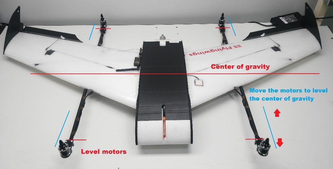
- Check the vehicle is balanced around the expected centre of gravity
Hold the vehicle with your fingers at the center of gravity and check that the vehicle remains stable.
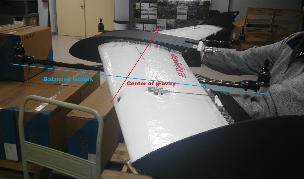
If the vehicle leans forward or backwards, move the motors to balance it.
설정
Perform the normal Basic Configuration.
Notes:
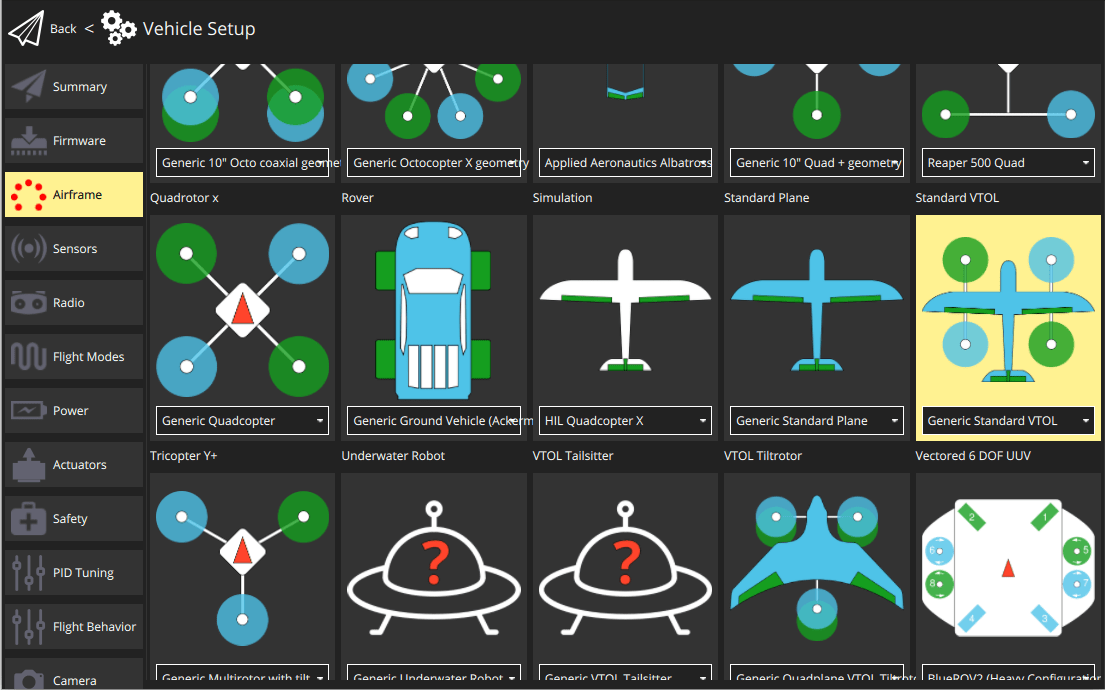
For Airframe select the vehicle group/type as Standard VTOL and the specific vehicle as Generic Standard VTOL as shown below.
Set the Autopilot Orientation to
ROTATION_YAW_270as the autopilot is mounted sideways with respect to the front of the vehicle. The compass is oriented forward, so you can leave that at the default (ROTATION_NONE).Configure the outputs and geometry following the instructions in Actuators Configuration
The default parameters are often sufficient for stable flight. For more detailed tuning information see Standard VTOL Wiring and Configuration.
After you finish calibration the VTOL is ready to fly.