MC Filter Tuning & Control Latency
Filters can be used to trade off control latency, which affects flight performance, and noise filtering, which impacts both flight performance and motor health.
제어 지연과 PX4 필터 튜닝에 관한 개요를 제공합니다.
INFO
Before filter tuning you should do a first pass at Basic MC PID tuning. The vehicle needs to be undertuned (the P and D gains should be set too low), such that there are no oscillations from the controller that could be interpreted as noise (the default gains might be good enough).
제어 지연
The control latency is the delay from a physical disturbance of the vehicle until the motors react to the change.
TIP
Lowering latency allows you to increase the rate P gains, which results in better flight performance. 1/1000초의 지연 시간도 큰 영향을 미칠 수 있습니다.
다음의 요소들은 제어 지연에 영향을 끼칩니다.
- 부드러운 기체 또는 부드러운 진동 장착은 대기 시간을 증가시킵니다 (필터 역할을 함).
- 소프트웨어 및 센서 칩의 저역 통과 필터는 대기 시간 증가분을 상쇄하여 노이즈 필터링을 원활하게합니다.
- PX4 소프트웨어 내부 : 센서 신호를 드라이버에서 읽은 다음 컨트롤러를 통해 출력 드라이버로 전달하여야 합니다.
- The maximum gyro publication rate (configured with IMU_GYRO_RATEMAX). 속도가 높을수록 지연 시간이 줄어들지만 증간된 연산량으로 인하여 다른 프로세스를 방해할 수 있습니다. 4kHz 이상은 STM32H7 프로세서 이상의 컨트롤러에서만 권장됩니다 (2kHz 값은 성능이 낮은 프로세서의 최대치입니다).
- The IO chip (MAIN pins) adds about 5.4 ms latency compared to using the AUX pins (this does not apply to a Pixracer or Omnibus F4, but does apply to a Pixhawk). To avoid the IO delay attach the motors to the AUX pins instead.
- PWM output signal: enable Dshot by preference to reduce latency (or One-Shot if DShot is not supported). The protocol is selected for a group of outputs during Actuator Configuration.
아래에서는 저역 통과 필터의 효과에 대하여 설명합니다.
필터
The filtering pipeline for the controllers in PX4 is described below.
INFO
Sampling and filtering is always performed at the full raw sensor rate (commonly 8kHz, depending on the IMU).
On-chip DLPF for the Gyro Sensor
This is disabled on all chips where it can be disabled (if not, cutoff frequency is set to the highest level of the chip).
Notch Filters
상당한 저주파 노이즈 스파이크가있는 설정 (예 : 로터 블레이드 통과 주파수의 고조파로 인한)은 노치 필터를 사용하여 신호가 저역 통과 필터로 전달되기 전에 신호를 제거하는 것이 좋습니다 (이러한 고조파는 다른 소음원으로 모터에서 비슷한 해로운 영향을 미칩니다).
Without the notch filter you'd have to set the low pass filter cutoff much lower (increasing the phase lag) in order to avoid passing this noise to the motors.
Static Notch Filters
One or two static notch filters on the gyro sensor data that are used to filter out narrow band noise, for example a bending mode of the airframe.
The static notch filters can be configured using:
- First notch filter: IMU_GYRO_NF0_BW and IMU_GYRO_NF0_FRQ.
- Second notch filter: IMU_GYRO_NF1_BW and IMU_GYRO_NF1_FRQ.
INFO
Only two notch filters are provided. Airframes with more than two frequency noise spikes typically clean the first two spikes with the notch filters, and subsequent spikes using the low pass filter.
Dynamic Notch Filters
Dynamic notch filters use ESC RPM feedback and/or the onboard FFT analysis. The ESC RPM feedback is used to track the rotor blade pass frequency and its harmonics, while the FFT analysis can be used to track a frequency of another vibration source, such as a fuel engine.
ESC RPM feedback requires ESCs capable of providing RPM feedback such as DShot with telemetry connected, a bidirectional DShot set up (work in progress), or UAVCAN/DroneCAN ESCs. Before enabling, make sure that the ESC RPM is correct. You might have to adjust the pole count of the motors.
The following parameters should be set to enable and configure dynamic notch filters:
| 매개변수 | 설명 |
|---|---|
| IMU_GYRO_DNF_EN | Enable IMU gyro dynamic notch filtering. 0: ESC RPM, 1: Onboard FFT. |
| IMU_GYRO_FFT_EN | Enable onboard FFT (required if IMU_GYRO_DNF_EN is set to 1). |
| IMU_GYRO_DNF_MIN | Minimum dynamic notch frequency in Hz. |
| IMU_GYRO_DNF_BW | Bandwidth for each notch filter in Hz. |
| IMU_GYRO_DNF_HMC | Number of harmonics to filter. |
Low-pass Filter
A low pass filter on the gyro data can be configured with the IMU_GYRO_CUTOFF parameter.
제어 지연을 줄이기 위해 저역 통과 필터의 차단 주파수를 높이려고 합니다. The effect on latency of increasing IMU_GYRO_CUTOFF is approximated below.
| Cutoff (Hz) | 지연(대략). (ms) |
|---|---|
| 30 | 8 |
| 60 | 3.8 |
| 120 | 1.9 |
However this is a trade-off as increasing IMU_GYRO_CUTOFF will also increase the noise of the signal that is fed to the motors. 모터 소음은 다음과 같은 결과를 가져옵니다.
- 모터와 ESC는 손상될 정도로 뜨거워 질 수 있습니다.
- 모터가 계속 속도를 변경하므로 비행 시간이 단축됩니다.
- 가시적인 임의의 작은 트위치.
Low-pass Filter on D-term
D-term은 노이즈에 가장 취약하지만 대기 시간이 약간 증가해도 성능에 나쁜 영향을 주지 않습니다. For this reason the D-term has a separately-configurable low-pass filter, IMU_DGYRO_CUTOFF.
Slew-rate Filter on Motor Outputs
An optional slew-rate filter on the motor outputs. This rate may be configured as part of the Multicopter Geometry when configuring actuators (which in turn modifies the CA_Rn_SLEW parameters for each motor n).
필터 튜닝
INFO
최적의 필터 설정은 기체에 따라 달라집니다. 기본값은 낮은 품질 설정에서도 작동하도록 보수적으로 설정됩니다.
First make sure to have the high-rate logging profile activated (SDLOG_PROFILE parameter). Flight Review will then show an FFT plot for the roll, pitch and yaw controls.
WARNING
- 기체의 심한 진동 문제를 필터 튜닝만으로 해결하는 것은 적절하지 않습니다. 기체의 하드웨어 설정을 수정하는 것이 바람직합니다.
- PID 게인, 특히 D가 진동으로 나타날 수 있으므로 너무 높게 설정되지 않았는 지 확인하십시오.
필터 튜닝은 비행 로그를 검토하는 것이 제일 좋은 방법입니다. 서로 다른 매개 변수를 사용하여 여러 차례 비행후 로그를 분석할 수 있지만, 별도의 로그 파일이 생성되도록 중간에 시동을 꺼야합니다.
The performed flight manoeuvre can simply be hovering in Stabilized mode with some rolling and pitching to all directions and some increased throttle periods. 전체 시간은 30초를 넘지 않아도 됩니다. In order to better compare, the manoeuvre should be similar in all tests.
First tune the gyro filter IMU_GYRO_CUTOFF by increasing it in steps of 10 Hz while using a low D-term filter value (IMU_DGYRO_CUTOFF = 30). Upload the logs to Flight Review and compare the Actuator Controls FFT plot. 노이즈가 눈에 띄게 증가하기 전에 차단 주파수를 설정하십시오 (60Hz 주변 및 그 이상의 주파수).
Then tune the D-term filter (IMU_DGYRO_CUTOFF) in the same way. Note that there can be negative impacts on performance if IMU_GYRO_CUTOFF and IMU_DGYRO_CUTOFF are set too far apart (the differences have to be significant though - e.g. D=15, gyro=80).
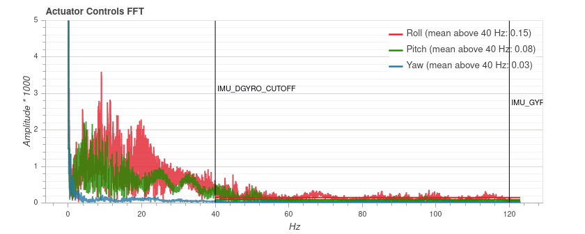
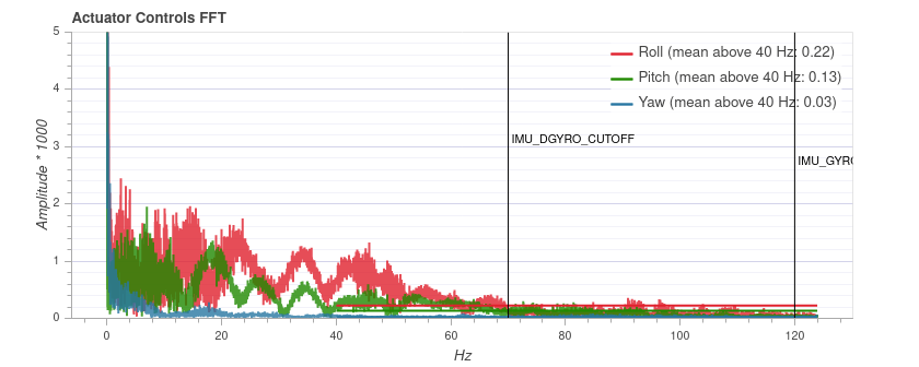
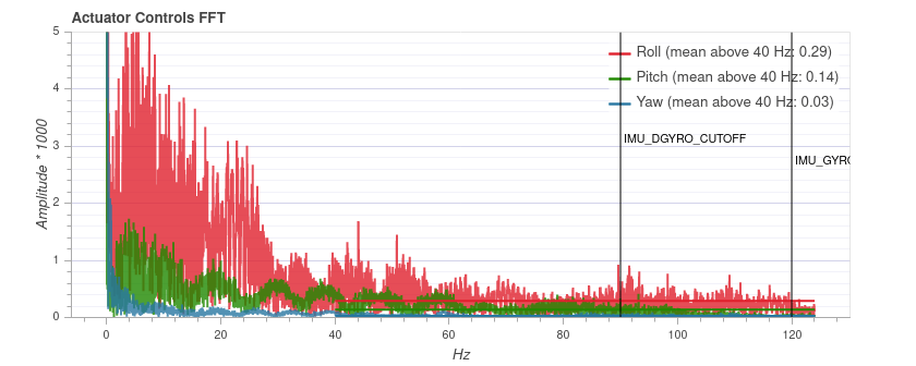
Below is an example for three different IMU_DGYRO_CUTOFF filter values (40Hz, 70Hz, 90Hz). 90Hz에서는 일반적인 소음이 증가하기 시작하므로 (특히 롤의 경우) 차단 주파수 70Hz가 안전합니다. 


INFO
The plot cannot be compared between different vehicles, as the y axis scale can be different. 동일한 기체에서 일관적이며 비행 시간과는 무관합니다.
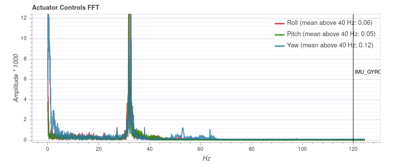
아래 다이어그램에 표시된 것과 같이 비행 플롯에 상당한 저주파 스파이크가 나타되는 경우에는 노치 필터를 사용하여 제거할 수 있습니다. In this case you might use the settings: IMU_GYRO_NF0_FRQ=32 and IMU_GYRO_NF0_BW=5 (note, this spike is narrower than usual). 저역 통과 필터와 노치 필터는 독립적으로 조정할 수 있습니다 (즉, 저역 통과 필터를 조정하기 전에 노치 필터를 설정할 필요는 없습니다).

추가 팁
허용 가능한 지연 시간은 기체 크기와 기대치에 따라 달라집니다. FPV racers typically tune for the absolute minimal latency (as a ballpark
IMU_GYRO_CUTOFFaround 120,IMU_DGYRO_CUTOFFof 50 to 80). For bigger vehicles latency is less critical andIMU_GYRO_CUTOFFof around 80 might be acceptable.You can start tuning at higher
IMU_GYRO_CUTOFFvalues (e.g. 100Hz), which might be desirable because the default tuning ofIMU_GYRO_CUTOFFis set very low (30Hz). 유일한 주의 사항은 위험을 알고 있어야한다는 것입니다.- 20 ~ 30 초 이상 비행하지 마십시오
- 모터가 과열되지 않는 지 확인하십시오.
- 위의 설명처럼 이상한 소리와 과도한 소음을 체크하십시오.