멀티콥터 PID 튜닝 가이드
This tutorial explains how to manually tune the PID loops on PX4 for all multicopter setups (Quads, Hexa, Octo etc).
TIP
Autotune is recommended for most users, as it is far faster, easier and provides good tuning for most frames. 예를 들어, 새로운 ESC 또는 모터에는 다른 튜닝 게인이 필요합니다.
Generally if you're using an appropriate supported frame configuration, the default tuning should allow you to fly the vehicle safely. Tuning is recommended for all new vehicle setups to get the very best performance, because relatively small hardware and assembly changes can affect the gains required tuning gains for optimal flight. For example, different ESCs or motors change the optimal tuning gains.
소개
PX4 uses Proportional, Iintegral, Derivative (PID) controllers (these are the most widespread control technique).
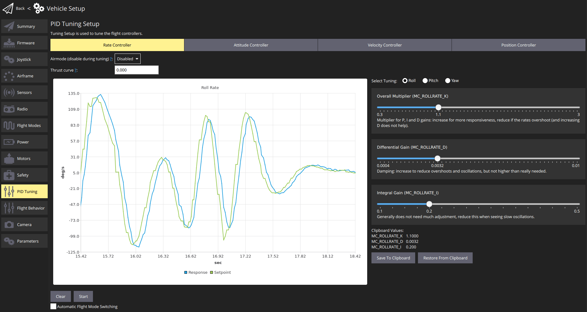
The QGroundControl PID Tuning setup provides real-time plots of the vehicle setpoint and response curves. The goal of tuning is to set the P/I/D values such that the Response curve matches the Setpoint curve as closely as possible (i.e. a fast response without overshoots).
컨트롤러는 계층화되어 있어 상위 수준의 컨트롤러 결과를 하위 수준의 컨트롤러로 전달합니다. The lowest-level controller is the rate controller, followed by the attitude controller, and finally the velocity & position controller. PID 튜닝은 다른 모든 컨트롤러에 영향을 미치므로 속도 컨트롤러부터 시작하여 동일한 순서로 수행해야합니다.
The testing procedure for each controller (rate, attitude, velocity/position) and axis (yaw, roll, pitch) is always the same: create a fast setpoint change by moving the sticks very rapidly and observe the response. 가장 낮은 수준의 컨트롤러는 속도 컨트롤러, 태도 컨트롤러, 마지막으로 속도 & 위치 컨트롤러 입니다.
TIP
- 속도 컨트롤러 조정이 가장 중요하며 잘 조정된 경우 다른 컨트롤러는 종종 약간의 조정만 필요하거나 필요하지 않습니다.
- 일반적으로 롤 및 피치에 동일한 튜닝 게인을 사용할 수 있습니다.
- 곡예/안정화/고도 모드를 사용하여 속도 컨트롤러 조정
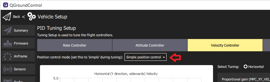
- Use Position mode to tune the Velocity Controller and the Position Controller. Make sure to switch to the Simple position control mode so you can generate step inputs.
전제 조건
You have selected the closest matching default frame configuration for your vehicle. This should give you a vehicle that already flies.
You should have done an ESC calibration.
If using PWM outputs their minimum values should be set correctly in the Actuator Configuration. These need to be set low, but such that the motors never stop when the vehicle is armed.
This can be tested in Acro mode or in Stabilized mode:
- Remove propellers
- Arm the vehicle and lower the throttle to the minimum
- Tilt the vehicle to all directions, about 60 degrees
- Check that no motors turn off
Use a high-rate telemetry link such as WiFi if at all possible (a typical low-range telemetry radio is not fast enough for real-time feedback and plots). This is particularly important for the rate controller.
Disable MC_AIRMODE before tuning a vehicle (there is an options for this in the PID tuning screen).
WARNING
Poorly tuned vehicles are likely to be unstable, and easy to crash. Make sure to have assigned a Kill switch.
Tuning Procedure
The tuning procedure is:
Arm the vehicle, takeoff, and hover (typically in Position mode).
Open QGroundControl Vehicle Setup > PID Tuning
Select the Rate Controller tab.
Confirm that the airmode selector is set to Disabled
Set the Thrust curve value to: 0.3 (PWM, power-based controllers) or 1 (RPM-based ESCs)
INFO
For PWM, power-based and (some) UAVCAN speed controllers, the control signal to thrust relationship may not be linear. As a result, the optimal tuning at hover thrust may not be ideal when the vehicle is operating at higher thrust.
The thrust curve value can be used to compensate for this non-linearity:
- For PWM controllers, 0.3 is a good default (which may benefit from further tuning).
- For RPM-based controllers, use 1 (no further tuning is required as these have a quadratic thrust curve).
For more information see the detailed PID tuning guide.
:::
Set the Select Tuning radio button to: Roll.
(Optionally) Select the Automatic Flight Mode Switching checkbox. This will automatically switch from Position mode to Stabilised mode when you press the Start button
For rate controller tuning switch to Acro mode, Stabilized mode or Altitude mode (unless automatic switching is enabled).
Select the Start button in order to start tracking the setpoint and response curves.
Rapidly move the roll stick full range and observe the step response on the plots.
TIP
Stop tracking to enable easier inspection of the plots. This happens automatically when you zoom/pan. Use the Start button to restart the plots, and Clear to reset them.
:::
Modify the three PID values using the sliders (for roll rate-tuning these affect
MC_ROLLRATE_K,MC_ROLLRATE_I,MC_ROLLRATE_D) and observe the step response again. The values are saved to the vehicle as soon as the sliders are moved.INFO
The goal is for the Response curve to match the Setpoint curve as closely as possible (i.e. a fast response without overshoots).
:::
The PID values can be adjusted as follows:

- P (비례) 또는 K 이득 :
  - 더 많은 응답을 위해 이것을 늘리십시오.
  - 응답이 오버 슈팅 및/또는 진동하는 경우 감소합니다 (특정 지점까지 D 게인 증가도 도움이 됨).
- D (미분) 이득 :
  - 오버슈트 및 진동을 줄이기 위해이 값을 늘릴 수 있습니다.
  - 소음을 증폭하고 모터가 뜨거워 질 수 있으므로 필요한 만큼만 늘리십시오.
- I (적분) 이득 :
  - 정상 상태 오류를 줄이는 데 사용
  - 너무 낮으면 응답이 설정 값에 도달하지 못할 수 있습니다 (예 : 바람)
  - 너무 높으면 느린 진동이 발생할 수 있습니다.
- 피치와 요에 대해 위의 튜닝 프로세스를 반복합니다.
- Use Select Tuning radio button to select the axis to tune
- 적절한 스틱을 이동합니다 (예 : 피치 스틱, 요 스틱).
- 피치 튜닝의 경우 롤과 동일한 값으로 시작하십시오.
TIP
Use the Save to Clipboard and Reset from Clipboard buttons to copy the roll settings for initial pitch settings.
:::
모든 축에서 자세 콘트롤러에 대하여 튜닝 프로세스를 반복하십시오.
Repeat the tuning process for the velocity and positions controllers (on all the axes).
Use Position mode when tuning these controllers
Select the Simple position control option in the Position control mode ... selector (this allows direct control for the generation of step inputs)
완료되었습니다 ! 설정을 종료하기 전에 에어 모드를 다시 활성화하여야 합니다.