Adding a Frame Configuration
PX4 frame configuration files are shell scripts that set up some (or all) of the parameters, controllers and apps needed for a particular vehicle frame, such as a quadcopter, ground vehicle, or boat. These scripts are executed when the corresponding airframe is selected and applied in QGroundControl.
The configuration files that are compiled into firmware for NuttX targets are located in the ROMFS/px4fmu_common/init.d folder (configuration files for POSIX simulators are stored in ROMFS/px4fmu_common/init.d-posix). The folder contains both complete and full configurations for specific vehicles, and partial "generic configurations" for different vehicle types. The generic configurations are often used as the starting point for creating new configuration files.
In addition, a frame configuration file can also be loaded from an SD card.
INFO
You can also "tweak" the current frame configuration using text files on the SD card. This is covered in System Startup > Customizing the System Startup page.
INFO
To determine which parameters/values need to be set in the configuration file, you can first assign a generic airframe and tune the vehicle, and then use param show-for-airframe to list the parameters that changed.
Developing a Frame Configuration
The recommended process for developing a new frame configuration is:
- Start by selecting an appropriate "generic configuration" for the target vehicle type in QGC, such as Generic Quadcopter.
- Configure the geometry and actuator outputs.
- Perform other basic configuration.
- Tune the vehicle.
- Run the
param show-for-airframeconsole command to list the parameter difference compared to the original generic airframe.
Once you have the parameters you can create a new frame configuration file by copying the configuration file for the generic configuration, and appending the new parameters.
Alternatively you can just append the modified parameters to the startup configuration files described in System Startup > Customizing the System Startup ("tweaking the generic configuration").
How to add a Configuration to Firmware
To add a frame configuration to firmware:
- Create a new config file in the init.d/airframes folder.
- Give it a short descriptive filename and prepend the filename with an unused autostart ID (for example,
1033092_superfast_vtol). - Update the file with configuration parameters and apps (see section above).
- Give it a short descriptive filename and prepend the filename with an unused autostart ID (for example,
- Add the name of the new frame config file to the CMakeLists.txt in the relevant section for the type of vehicle.
- Build and upload the software.
How to add a Configuration to an SD Card
A frame configuration file to be launched from SD card is the same as one stored in firmware.
To make PX4 launch with a frame configuration, renamed it to rc.autostart and copy it to the SD card at /ext_autostart/rc.autostart. PX4 will find any linked files in firmware.
구성 파일 개요
The configuration file consists of several main blocks:
- Documentation (used in the Airframes Reference and QGroundControl). Airframe-specific parameter settings
- The configuration and geometry using control allocation parameters
- Tuning gains
- The controllers and apps it should start, such as multicopter or fixed-wing controllers, land detectors etc.
이러한 측면은 대부분 독립적이므로, 많은 구성이 기체의 동일한 물리적 레이아웃을 공유하고 동일한 응용 프로그램을 시작하며 튜닝 이득이 가장 차이가 납니다.
INFO
New frame configuration files are only automatically added to the build system after a clean build (run make clean).
Force Reset of Airframe Parameters on Update
To force a reset to the airframe defaults for all users of a specific airframe during update, increase the PARAM_DEFAULTS_VER variable in the airframe configuration. It starts at 1 in rcS. Add set PARAM_DEFAULTS_VER 2 in your airframe file, increasing the value with each future reset needed.
This value is compared to SYS_PARAM_VER during PX4 updates. If different, user-customized parameters are reset to defaults.
Note that system parameters primarily include those related to the vehicle airframe configuration. Parameters such as accumulating flight hours, RC and sensor calibrations, are preserved.
Example - Generic Quadcopter Frame Config
The configuration file for a generic Quad X copter is shown below (original file here). This is very simple, because it defines only the minimal setup common to all quadcopters.
The first line is a shebang, which tells the NuttX operating system (on which PX4 runs) that the configuration file is an executable shell script.
#!/bin/shThis is followed by the frame documentation. The @name, @type and @class are used to identify and group the frame in the API Reference and QGroundControl Airframe Selection.
# @name Generic Quadcopter
#
# @type Quadrotor x
# @class Copter
#
# @maintainer Lorenz Meier <lorenz@px4.io>
#
The next line imports generic parameters that are appropriate for all vehicles of the specified type (see init.d/rc.mc_defaults).
. ${R}etc/init.d/rc.mc_defaultsFinally the file lists the control allocation parameters (starting with CA_ that define the default geometry for the frame. These may be modified for your frame geometry in the Actuators Configuration, and output mappings may be added.
param set-default CA_ROTOR_COUNT 4
param set-default CA_ROTOR0_PX 0.15
param set-default CA_ROTOR0_PY 0.15
param set-default CA_ROTOR1_PX -0.15
param set-default CA_ROTOR1_PY -0.15
param set-default CA_ROTOR2_PX 0.15
param set-default CA_ROTOR2_PY -0.15
param set-default CA_ROTOR2_KM -0.05
param set-default CA_ROTOR3_PX -0.15
param set-default CA_ROTOR3_PY 0.15
param set-default CA_ROTOR3_KM -0.05
Example - HolyBro QAV250 Complete Vehicle
A more complete configuration file for a real vehicle is provided below. This is the configuration for the HolyBro QAV250 quadrotor (original file here).
The shebang and documentation sections are similar to those for the generic frame. Here we also add a @url link to the vehicle documentation, a @maintainer, and additional board exclusions.
#!/bin/sh
#
# @name HolyBro QAV250
#
# @url https://docs.px4.io/main/en/frames_multicopter/holybro_qav250_pixhawk4_mini
#
# @type Quadrotor x
# @class Copter
#
# @maintainer Beat Kueng <beat-kueng@gmx.net>
#
# @board px4_fmu-v2 exclude
# @board bitcraze_crazyflie exclude
# @board px4_fmu-v6x exclude
# @board ark_fmu-v6x exclude
#
Next, we source the multicopter defaults.
. ${R}etc/init.d/rc.mc_defaultsThen we define configuration parameters and tuning gains:
# The set does not include a battery, but most people will probably use 4S
param set-default BAT1_N_CELLS 4

param set-default IMU_GYRO_CUTOFF 120
param set-default IMU_DGYRO_CUTOFF 45

param set-default MC_AIRMODE 1
param set-default MC_PITCHRATE_D 0.0012
param set-default MC_PITCHRATE_I 0.35
param set-default MC_PITCHRATE_MAX 1200
param set-default MC_PITCHRATE_P 0.082
param set-default MC_PITCH_P 8
param set-default MC_ROLLRATE_D 0.0012
param set-default MC_ROLLRATE_I 0.3
param set-default MC_ROLLRATE_MAX 1200
param set-default MC_ROLLRATE_P 0.076
param set-default MC_ROLL_P 8
param set-default MC_YAWRATE_I 0.3
param set-default MC_YAWRATE_MAX 600
param set-default MC_YAWRATE_P 0.25
param set-default MC_YAW_P 4

param set-default MPC_MANTHR_MIN 0
param set-default MPC_MAN_TILT_MAX 60
param set-default MPC_THR_CURVE 1
param set-default MPC_THR_HOVER 0.25
param set-default MPC_THR_MIN 0.05
param set-default MPC_Z_VEL_I_ACC 1.7

param set-default THR_MDL_FAC 0.3
Last of all, the file defines the control allocation parameters for the geometry and the parameters that set which outputs map to different motors.
# Square quadrotor X PX4 numbering
param set-default CA_ROTOR_COUNT 4
param set-default CA_ROTOR0_PX 1
param set-default CA_ROTOR0_PY 1
param set-default CA_ROTOR1_PX -1
param set-default CA_ROTOR1_PY -1
param set-default CA_ROTOR2_PX 1
param set-default CA_ROTOR2_PY -1
param set-default CA_ROTOR2_KM -0.05
param set-default CA_ROTOR3_PX -1
param set-default CA_ROTOR3_PY 1
param set-default CA_ROTOR3_KM -0.05

param set-default PWM_MAIN_FUNC1 101
param set-default PWM_MAIN_FUNC2 102
param set-default PWM_MAIN_FUNC3 103
param set-default PWM_MAIN_FUNC4 104
새 기체 그룹 추가
Airframe "groups" are used to group similar airframes for selection in QGroundControl and in the Airframe Reference. 모든 그룹에는 그룹화된 기체에 대한 공통 지오메트리, 모터 수, 및 모터 회전 방향을 나타내는 이름과 연관된 svg 이미지가 있습니다.
The airframe metadata files used by QGroundControl and the documentation source code are generated from the airframe description, via a script, using the build command: make airframe_metadata
For a new frame belonging to an existing group, you don't need to do anything more than provide documentation in the airframe description located at ROMFS/px4fmu_common/init.d.
If the airframe is for a new group you additionally need to:
Add the svg image for the group into user guide documentation (if no image is provided a placeholder image is displayed): assets/airframes/types
Add a mapping between the new group name and image filename in the srcparser.py method
GetImageName()(follow the pattern below):pythondef GetImageName(self): """ Get parameter group image base name (w/o extension) """ if (self.name == "Standard Plane"): return "Plane" elif (self.name == "Flying Wing"): return "FlyingWing" ... ... return "AirframeUnknown"Update QGroundControl:
Add the svg image for the group into: src/AutopilotPlugins/Common/images
Add a reference to the svg image into CMakeLists.txt, following the pattern below:
cmakeqt_add_resources(${CMAKE_PROJECT_NAME} autopilot_plugin_common_airframes PREFIX "/qmlimages/Airframe" BASE "${CMAKE_SOURCE_DIR}/src/AutoPilotPlugins/Common/Images" FILES "${CMAKE_SOURCE_DIR}/src/AutoPilotPlugins/Common/Images/AirframeSimulation.svg" "${CMAKE_SOURCE_DIR}/src/AutoPilotPlugins/Common/Images/AirframeUnknown.svg" "${CMAKE_SOURCE_DIR}/src/AutoPilotPlugins/Common/Images/Boat.svg" "${CMAKE_SOURCE_DIR}/src/AutoPilotPlugins/Common/Images/FlyingWing.svg" ... )INFO
The remaining airframe metadata should be automatically included in the firmware (once srcparser.py is updated).
:::
게인 튜닝
구성 파일에 지정될 매개변수를 조정하는 방법을 설명합니다.
- Autotuning (Multicopter) (or Multicopter PID Tuning Guide)
- Autotuning (Fixed-wing) (or Fixed-wing PID Tuning Guide)
- Autotuning (VTOL) (VTOL Configuration)
Add Frame to QGroundControl
To make a new airframe available for section in the QGroundControl frame configuration:
- Make a clean build (e.g. by running
make cleanand thenmake px4_fmu-v5_default) - Open QGC and select Custom firmware file... as shown below:
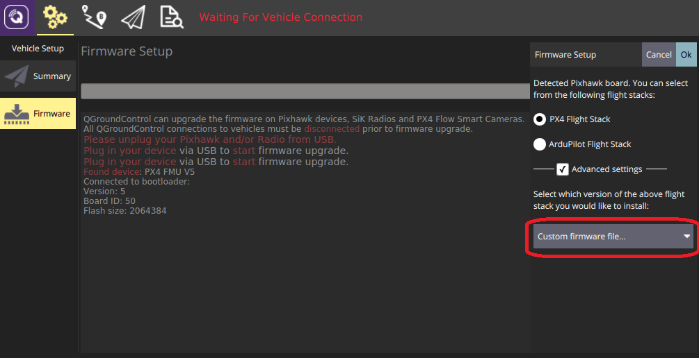
You will be asked to choose the .px4 firmware file to flash (this file is a zipped JSON file and contains the airframe metadata).
- Navigate to the build folder and select the firmware file (e.g. PX4-Autopilot/build/px4_fmu-v5_default/px4_fmu-v5_default.px4).
- Press OK to start flashing the firmware.
- Restart QGroundControl.
The new frame will then be available for selection in QGroundControl.