Holybro Pixhawk 4
WARNING
PX4 does not manufacture this (or any) autopilot. Contact the manufacturer for hardware support or compliance issues.
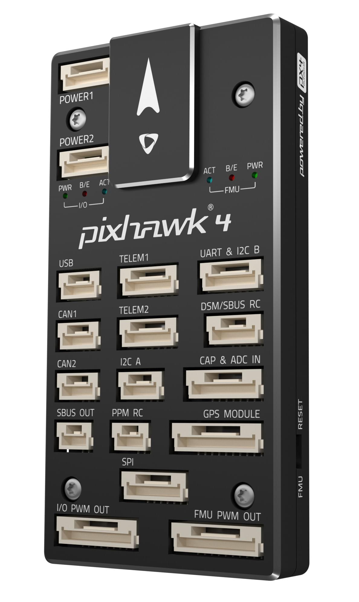
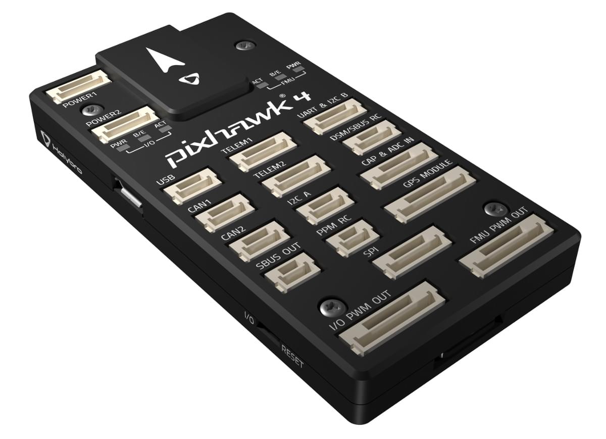
Pixhawk 4® is an advanced autopilot designed and made in collaboration with Holybro® and the PX4 team. PX4 v1.7 이상의 버전 실행에 최적화되어 있으며, 학계와 업계 개발자에게 적합합니다.
It is based on the Pixhawk-project FMUv5 open hardware design and runs PX4 on the NuttX OS.
TIP
This autopilot is supported by the PX4 maintenance and test teams.
요약
- 메인 FMU 프로세서: STM32F765
- 32 비트 Arm® Cortex®-M7, 216MHz, 2MB 메모리, 512KB RAM
- IO 프로세서: STM32F100
- 32 비트 Arm® Cortex®-M3, 24MHz, 8KB SRAM
- 내장 센서 :
- 가속도/자이로: ICM-20689
- Accel/Gyro: BMI055 or ICM20602
- 자력계 : IST8310
- 기압계: MS5611
- GPS: u-blox Neo-M8N GPS/GLONASS 수신기; 통합 자력계 IST8310
- 인터페이스:
- PWM 출력 8-16개(IO에서 8개, FMU에서 8개)
- FMU의 전용 PWM/캡처 입력 3 개
- CPPM 전용 RC 입력
- 아날로그/PWM RSSI 입력이있는 Spektrum/DSM 및 S.Bus 전용 RC 입력
- Dedicated S.Bus servo output
- 범용 시리얼 포트 5개
- I2C 포트 3개
- SPI 버스 4개
- 직렬 ESC를 사용하는 듀얼 CAN에 최대 2 개의 CAN 버스
- 배터리 2 개의 전압 및 전류에 대한 아날로그 입력
- 전원시스템
- 전원 모듈 출력: 4.9~5.5V
- USB 전원 입력: 4.75~5.25V
- 서보 레일 입력: 0~36V
- 중량과 크기
- 무게: 15.8g
- 크기: 44x84x12mm
- 기타 특성:
- 작동 온도: -40 ~ 85°c
Additional information can be found in the Pixhawk 4 Technical Data Sheet.
구매처
Order from Holybro.
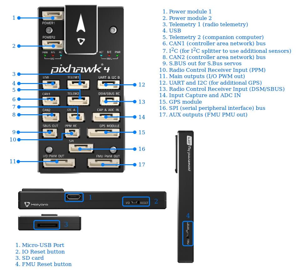
커넥터
WARNING
The DSM/SBUS RC and PPM RC ports are for RC receivers only. 이 포트들에는 전원이 공급됩니다. 서보를 전원공급장치나 배터리(또는 연결된 수신기)에 절대 연결하지 마십시오.
핀배열
Download Pixhawk 4 pinouts from here.
INFO
Connector pin assignments are left to right (i.e. Pin 1 is the left-most pin). The exception is the debug port(s) (pin 1 is the right-most, as shown below).
시리얼 포트 매핑
| UART | 장치 | 포트 |
|---|---|---|
| UART1 | /dev/ttyS0 | GPS |
| USART2 | /dev/ttyS1 | TELEM1 (흐름 제어) |
| USART3 | /dev/ttyS2 | TELEM2 (흐름 제어) |
| UART4 | /dev/ttyS3 | TELEM4 |
| USART6 | /dev/ttyS4 | RC SBUS |
| UART7 | /dev/ttyS5 | 디버그 콘솔 |
| UART8 | /dev/ttyS6 | PX4IO |
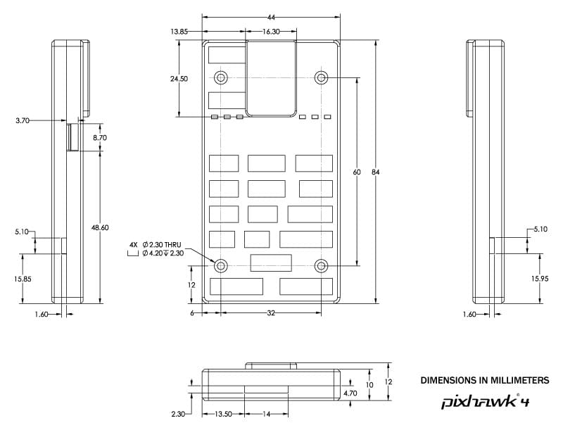
크기
정격 전압
Pixhawk 4 can be triple-redundant on the power supply if three power sources are supplied. The three power rails are: POWER1, POWER2 and USB.
INFO
The output power rails FMU PWM OUT and I/O PWM OUT (0V to 36V) do not power the flight controller board (and are not powered by it). You must supply power to one of POWER1, POWER2 or USB or the board will be unpowered.
Normal Operation Maximum Ratings
이러한 조건에서 전원은 아래의 순서대로 시스템에 전원을 공급하여야합니다.
- POWER1 and POWER2 inputs (4.9V to 5.5V)
- USB input (4.75V to 5.25V)
Absolute Maximum Ratings
아래의 조건에서 시스템은 전원을 사용하지 않지만(작동하지 않음), 그대로 유지됩니다.
- POWER1 and POWER2 inputs (operational range 4.1V to 5.7V, 0V to 10V undamaged)
- USB input (operational range 4.1V to 5.7V, 0V to 6V undamaged)
- Servo input: VDD_SERVO pin of FMU PWM OUT and I/O PWM OUT (0V to 42V undamaged)
조립 및 설정
The Pixhawk 4 Wiring Quick Start provides instructions on how to assemble required/important peripherals including GPS, Power Management Board etc.
펌웨어 빌드
TIP
Most users will not need to build this firmware! It is pre-built and automatically installed by QGroundControl when appropriate hardware is connected.
To build PX4 for this target:
make px4_fmu-v5_default디버그 포트
The PX4 System Console and SWD interface run on the FMU Debug port, while the I/O console and SWD interface can be accessed via I/O Debug port. In order to access these ports, the user must remove the Pixhawk 4 casing.
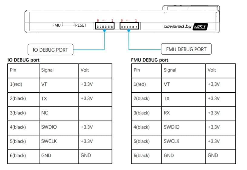
The pinout uses the standard Pixhawk debug connector pinout. 배선 정보는 다음을 참조하십시오.
주변 장치
지원 플랫폼 및 기체
일반 RC 서보 또는 Futaba S-Bus 서보로 제어 가능한 모든 멀티콥터/비행기/로버 또는 보트. The complete set of supported configurations can be seen in the Airframes Reference.