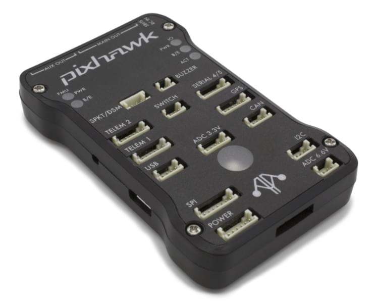
mRo Pixhawk 비행 컨트롤러 (Pixhawk 1)
WARNING
PX4 does not manufacture this (or any) autopilot. Contact the manufacturer for hardware support or compliance issues.
The mRo Pixhawk® is a hardware compatible version of the original Pixhawk 1. It runs PX4 on the NuttX OS.
TIP
The controller can be used as a drop-in replacement for the 3DR® Pixhawk 1. The main difference is that it is based on the Pixhawk-project FMUv3 open hardware design, which corrects a bug that limited the original Pixhawk 1 to 1MB of flash.
Assembly/setup instructions for use with PX4 are provided here: Pixhawk Wiring Quickstart
TIP
This autopilot is supported by the PX4 maintenance and test teams.
주요 특징
마이크로 프로세서:
- FPU가있는 32 비트 STM32F427 코어 텍스® M4 코어
- 168 MHz / 256 KB RAM / 2 MB 플래시
- 32 비트 STM32F100 failsafe 코프로세서
- 24 MHz/8 KB RAM/64 KB 플래시
센서:
- ST Micro L3GD20 3축 16비트 자이로스코프
- ST Micro LSM303D 3축 14비트 가속도계/자력계
- Invensense® MPU 6000 3축 가속도계/자이로스코프
- MEAS MS5611 기압계
인터페이스:
- UART (직렬 포트) 5개, 1 개의 고전력 지원, 2x (HW 흐름 제어 포함)
- CAN 2 개
- 최대 DX8의 Spektrum DSM/DSM2/DSM-X® Satellite 호환 입력(DX9 이상은 지원되지 않음)
- Futaba® S.BUS 호환 입력 및 출력
- PPM 합계 신호
- RSSI(PWM 또는 전압) 입력
- I2C
- SPI
- 3.3 및 6.6V ADC 입력
- 외부 microUSB 포트
전원시스템
- 자동 복구 기능의 이상적인 다이오드 컨트롤러
- 서보 레일 고전력 (7V) 및 고전류 준비
- 모든 주변 장치 출력 과전류 보호, 모든 입력 ESD 보호
중량과 크기
- 무게 : 38g (1.31oz)
- 너비 : 50mm (1.96 ")
- 두께 : 15.5mm (.613 ")
- 길이 : 81.5mm (3.21")
구매처
- Bare Bones - Just the board (useful as a 3DR Pixhawk replacement)
- mRo Pixhawk 2.4.6 Essential Kit! - Everything except for telemetry radios
- mRo Pixhawk 2.4.6 Cool Kit! (Limited edition) - Everything you need including telemetry radios
펌웨어 빌드
TIP
Most users will not need to build this firmware! It is pre-built and automatically installed by QGroundControl when appropriate hardware is connected.
To build PX4 for this target:
make px4_fmu-v3_default디버그 포트
콘솔 포트
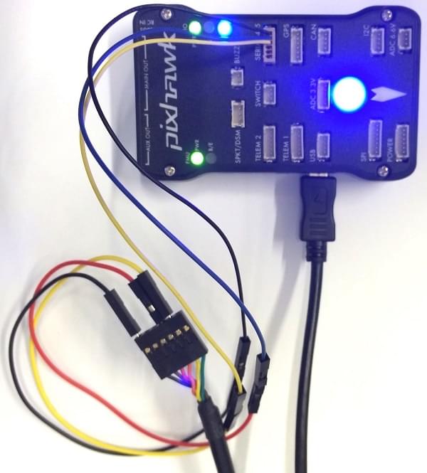
The PX4 System Console runs on the port labeled SERIAL4/5.
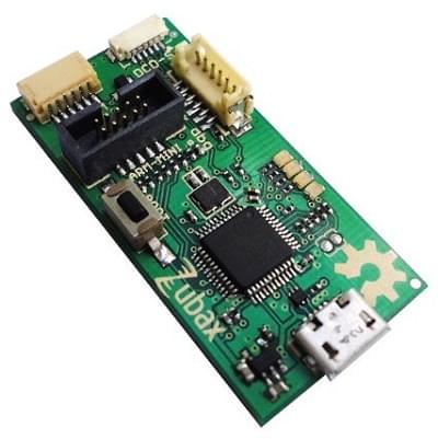
TIP
A convenient way to connect to the console is to use a Zubax BugFace BF1, as it comes with connectors that can be used with several different Pixhawk devices. Simply connect the 6-pos DF13 1:1 cable on the Zubax BugFace BF1 to the Pixhawk SERIAL4/5 port.
The pinout is standard serial pinout, designed to connect to a 3.3V FTDI cable (5V tolerant).
| 3DR Pixhawk 1 | FTDI | ||
|---|---|---|---|
| 1 | +5V (적) | N/C | |
| 2 | S4 Tx | N/C | |
| 3 | S4 Rx | N/C | |
| 4 | S5 Tx | 5 | FTDI RX (황) |
| 5 | S5 Rx | 4 | FTDI TX (적황) |
| 6 | GND | 1 | FTDI GND (흑) |
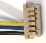
The wiring for an FTDI cable to a 6-pos DF13 1:1 connector is shown in the figure below.
The complete wiring is shown below.
INFO
For information on how to use the console see: System Console.
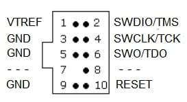
SWD 포트
The SWD (JTAG) ports are hidden under the cover (which must be removed for hardware debugging). There are separate ports for FMU and IO, as highlighted below.
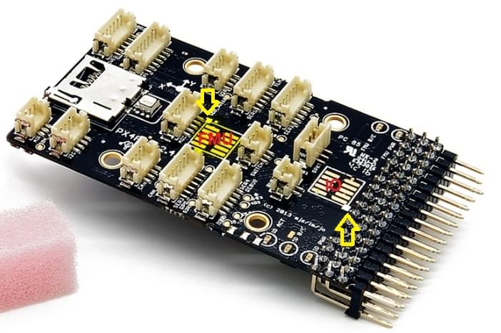
The ports are ARM 10-pin JTAG connectors, which you will probably have to solder. The pinout for the ports is shown below (the square markers in the corners above indicates pin 1).
INFO
All Pixhawk FMUv2 boards have a similar SWD port.
핀배열
TELEM1, TELEM2 포트
| 핀 | 신호 | 전압 |
|---|---|---|
| 1(red) | VCC | +5V |
| 2 (흑) | TX (출력) | +3.3V |
| 3 (흑) | RX (입력) | +3.3V |
| 4 (흑) | CTS (입력) | +3.3V |
| 5 (흑) | RTS (출력) | +3.3V |
| 6 (흑) | GND | GND |
GPS 포트
| 핀 | 신호 | 전압 |
|---|---|---|
| 1(red) | VCC | +5V |
| 2 (흑) | TX (출력) | +3.3V |
| 3 (흑) | RX (입력) | +3.3V |
| 4 (흑) | CAN2 TX | +3.3V |
| 5 (흑) | CAN2 RX | +3.3V |
| 6 (흑) | GND | GND |
SERIAL 4/5 port
Due to space constraints two ports are on one connector.
| 핀 | 신호 | 전압 |
|---|---|---|
| 1(red) | VCC | +5V |
| 2 (흑) | TX (#4) | +3.3V |
| 3 (흑) | RX (#4) | +3.3V |
| 4 (흑) | TX (#5) | +3.3V |
| 5 (흑) | RX (#5) | +3.3V |
| 6 (흑) | GND | GND |
ADC 6.6V
| 핀 | 신호 | 전압 |
|---|---|---|
| 1(red) | VCC | +5V |
| 2 (흑) | ADC 입력 | 최대 +6.6V |
| 3 (흑) | GND | GND |
ADC 3.3V
| 핀 | 신호 | 전압 |
|---|---|---|
| 1(red) | VCC | +5V |
| 2 (흑) | ADC 입력 | 최대 +3.3V |
| 3 (흑) | GND | GND |
| 4 (흑) | ADC 입력 | 최대 +3.3V |
| 5 (흑) | GND | GND |
I2C
| 핀 | 신호 | 전압 |
|---|---|---|
| 1(red) | VCC | +5V |
| 2 (흑) | SCL | +3.3 (풀업) |
| 3 (흑) | SDA | +3.3 (풀업) |
| 4 (흑) | GND | GND |
CAN
| 핀 | 신호 | 전압 |
|---|---|---|
| 1(red) | VCC | +5V |
| 2 (흑) | CAN_H | +12V |
| 3 (흑) | CAN_L | +12V |
| 4 (흑) | GND | GND |
SPI
| 핀 | 신호 | 전압 |
|---|---|---|
| 1(red) | VCC | +5V |
| 2 (흑) | SPI_EXT_SCK | +3.3 |
| 3 (흑) | SPI_EXT_MISO | +3.3 |
| 4 (흑) | SPI_EXT_MOSI | +3.3 |
| 5 (흑) | !SPI_EXT_NSS | +3.3 |
| 6 (흑) | !GPIO_EXT | +3.3 |
| 7 (흑) | GND | GND |
전원
| 핀 | 신호 | 전압 |
|---|---|---|
| 1(red) | VCC | +5V |
| 2 (흑) | VCC | +5V |
| 3 (흑) | CURRENT | +3.3V |
| 4 (흑) | VOLTAGE | +3.3V |
| 5 (흑) | GND | GND |
| 6 (흑) | GND | GND |
스위치
| 핀 | 신호 | 전압 |
|---|---|---|
| 1(red) | VCC | +3.3V |
| 2 (흑) | !IO_LED_SAFETY | GND |
| 3 (흑) | SAFETY | GND |
시리얼 포트 매핑
| UART | 장치 | 포트 |
|---|---|---|
| UART1 | /dev/ttyS0 | IO 디버그 |
| USART2 | /dev/ttyS1 | TELEM1 (흐름 제어) |
| USART3 | /dev/ttyS2 | TELEM2 (흐름 제어) |
| UART4 | ||
| UART7 | 콘솔 | |
| UART8 | SERIAL4 |
시리얼 포트 매핑
| UART | 장치 | 포트 |
|---|---|---|
| UART1 | /dev/ttyS0 | IO 디버그 |
| USART2 | /dev/ttyS1 | TELEM1 (흐름 제어) |
| USART3 | /dev/ttyS2 | TELEM2 (흐름 제어) |
| UART4 | ||
| UART7 | 콘솔 | |
| UART8 | SERIAL4 |
회로도
The board is based on the Pixhawk-project FMUv3 open hardware design.
- FMUv3 schematic -- Schematic and layout
INFO
As a CC-BY-SA 3.0 licensed Open Hardware design, all schematics and design files are available.