Holybro Durandal
WARNING
PX4 does not manufacture this (or any) autopilot. Contact the manufacturer for hardware support or compliance issues.
Durandal® is the latest update to the successful family of Holybro flight controllers. Holybro가 설계하고 개발하였습니다.
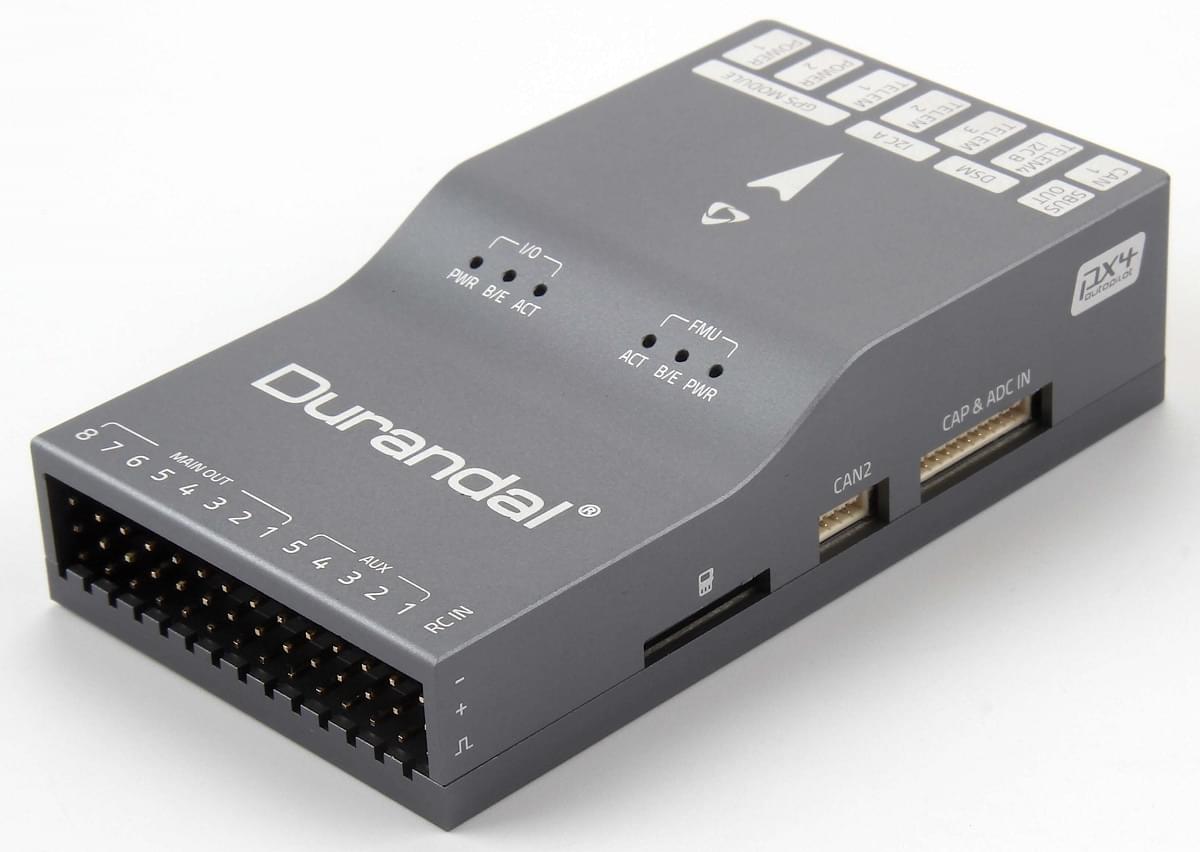
주요 기능은 다음과 같습니다.
- 센서 통합 온도 제어.
- 480MHz에서 실행되는 강력한 STM32H7 마이크로 컨트롤러. 2MB의 플래시 메모리 및 1MB의 RAM.
- 온도 안정성이 높은 신규 센서.
- 내부 진동 차단 시스템.
- 듀얼 고성능, 저잡음 IMU 온보드는 까다로운 안정화 애플리케이션을 위해 설계되었습니다.
A summary of the key features, assembly, and purchase links can be found below.
INFO
This flight controller is manufacturer supported.
요약
기술 사양
- 메인 FMU 프로세서: STM32H743
- 32 비트 Arm® Cortex® -M7, 480MHz, 2MB 메모리, 1MB RAM
- IO 프로세서: STM32F100
- 32 비트 Arm® Cortex®-M3, 24MHz, 8KB SRAM
- 내장 센서 :
- 가속도/자이로: ICM-20689
- Accel/Gyro: BMI088 or ICM20602
- 자력계: IST8310
- 기압계: MS5611
- GPS: u-blox Neo-M8N GPS/GLONASS 수신기; 통합 자력계 IST8310
인터페이스
- PWM 출력 8-13개(IO에서 8개, FMU에서 5개)
- FMU의 전용 PWM/캡처 입력 6 개
- Spektrum/DSM 전용 R/C 입력
- CPPM 및 S.Bus 전용 RC 입력
- 전용 S.Bus 서보 출력 및 아날로그/PWM RSSI 입력
- 범용 시리얼 포트 5개
- 전체 흐름 제어 3개
- 1.5A 전류 제한이 있는 1 개
- I2C 포트 3개
- SPI 버스 4개
- 4 개의 칩 선택 및 6 개의 DRDY가 있는 내부 고속 SPI 센서 버스 1 개
- XXX 전용 내부 저잡음 SPI 버스 1 개
- 2 개의 칩 선택이 있는 기압계, DRDY 없음
- FRAM 전용 내부 SPI 버스 1 개
- 센서 모듈에 위치한 온도 제어 지원
- 외부 SPI 버스 1개
- 듀얼 CAN을 위한 최대 2 개의 CAN 버스
- 각 CANBus에는 개별 무음 제어 또는 ESC RX-MUX 제어가 있습니다.
- 배터리 2 개의 전압 및 전류에 대한 아날로그 입력
- 2개의 추가 아날로그 입력
전기 데이터
- 전원 모듈 출력: 4.9~5.5V
- 최대 입력 전압: 6V
- 최대 전류 감지: 120A
- USB 전원 입력: 4.75~5.25V
- 서보 레일 입력: 0~36V
기계식 부품
- 크기: 80x45x20.5mm
- 중량: 68.8g
기타 특성
- 작동 온도 : ~ 40 ~ 85C
- 보관 온도 : -40 ~ 85C
- CE
- FCC
- RoHS 준수(무연)
For more information see: Durandal Technical Data Sheet.
구매처
Order from Holybro.
연결
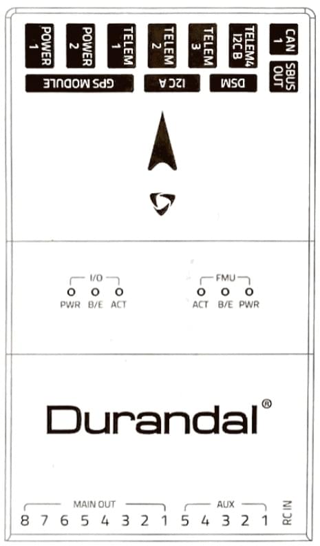
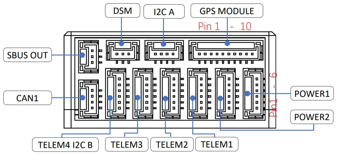
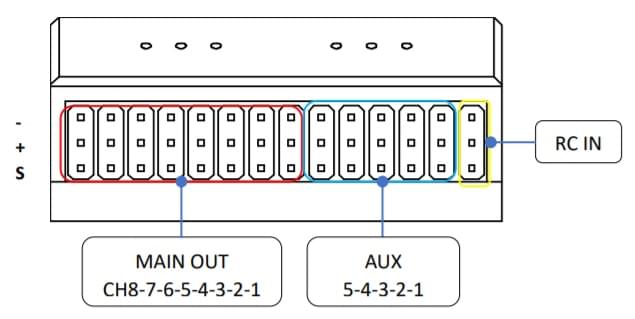
The locations of ports/connections are shown here (and below in the pinouts section).
상단
전면
후면
우측

좌측

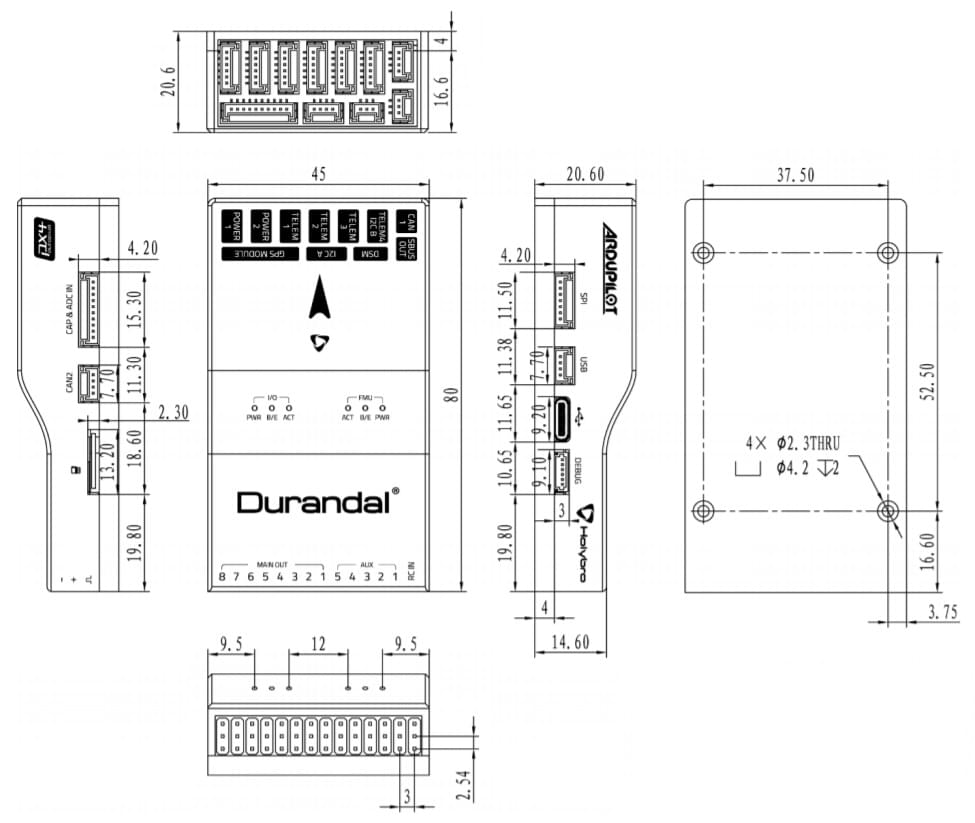
크기
모든 치수는 밀리미터 단위입니다.
조립 및 설정
The Durandal Wiring Quick Start provides instructions on how to assemble required/important peripherals including GPS, Power Management Board etc.
펌웨어 빌드
TIP
Most users will not need to build this firmware! It is pre-built and automatically installed by QGroundControl when appropriate hardware is connected.
To build PX4 for this target:
make holybro_durandal-v1_default시리얼 포트 매핑
| UART | 장치 | 포트 |
|---|---|---|
| USART1 | /dev/ttyS0 | GPS1 |
| USART2 | /dev/ttyS1 | TELEM1 |
| USART3 | /dev/ttyS2 | TELEM2 |
| UART4 | /dev/ttyS3 | TELEM4/GPS2 |
| USART6 | /dev/ttyS4 | TELEM3 |
| UART7 | /dev/ttyS5 | 디버그 콘솔 |
| UART8 | /dev/ttyS6 | PX4IO |
Debug Port
The PX4 System Console and SWD interface run on the Debug Port.
The pinouts and connector comply with the Pixhawk Debug Mini interface defined in the Pixhawk Connector Standard.
For wiring and debugging information see the above links.
INFO
No Debug port is exposed for the I/O board.
주변 장치
지원 플랫폼 및 기체
일반 RC 서보 또는 Futaba S-Bus 서보로 제어 가능한 모든 멀티콥터/비행기/로버 또는 보트.
The complete set of supported configurations can be seen in the Airframes Reference.
핀배열
Durandal pinouts are listed below. These can also be downloaded from here.
상단 핀배열

전면 핀배열

SUBS 출력 포트
| 핀 | 신호 | 전압 |
|---|---|---|
| 1(red) | - | - |
| 2 (황) | SBUS_OUT/RSSI_IN | +3.3V |
| 3 (흑) | GND | GND |
DSM RC 포트
| 핀 | 신호 | 전압 |
|---|---|---|
| 1(red) | VDD_3V3 | +3.3V |
| 2 (황) | DSM_IN | +3.3V |
| 3 (흑) | GND | GND |
I2C A 포트
| 핀 | 신호 | 전압 |
|---|---|---|
| 1(red) | VCC | +5V |
| 2 (흑) | SCL4 | +3.3V |
| 3 (흑) | SDA4 | +3.3V |
| 4 (흑) | GND | GND |
CAN1 포트
| 핀 | 신호 | 전압 |
|---|---|---|
| 1(red) | VCC | +5V |
| 2 (흑) | CAN H | +3.3V |
| 3 (흑) | CAN L | +3.3V |
| 4 (흑) | GND | GND |
GPS 포트
| 핀 | 신호 | 전압 |
|---|---|---|
| 1(red) | VCC | +5V |
| 2 (흑) | TX (출력) | +3.3V |
| 3 (흑) | RX (입력) | +3.3V |
| 4 (흑) | SCL1 | +3.3V |
| 5 (흑) | SDA1 | +3.3V |
| 6 (흑) | SAFETY_SWITCH | +3.3V |
| 7 (흑) | SAFETY_SWITCH_LED | +3.3V |
| 8 (흑) | VDD_3V3 | +3.3V |
| 9 (흑) | BUZZER | +5V |
| 10 (흑) | GND | GND |
TELEM4 I2CB 포트
| 핀 | 신호 | 전압 |
|---|---|---|
| 1(red) | VCC | +5V |
| 2 (흑) | TX (출력) | +3.3V |
| 3 (흑) | RX (입력) | - |
| 4 (흑) | SCL2 | - |
| 5 (흑) | SDA2 | +3.3V |
| 6 (흑) | GND | GND |
TELEM3, TELEM2, TELEM1 포트
| 핀 | 신호 | 전압 |
|---|---|---|
| 1(red) | VCC | +5V |
| 2 (흑) | TX (출력) | +3.3V |
| 3 (흑) | RX (입력) | +3.3V |
| 4 (흑) | CTS (입력) | +3.3V |
| 5 (흑) | RTS (출력) | +3.3V |
| 6 (흑) | GND | GND |
POWER 포트
| 핀 | 신호 | 전압 |
|---|---|---|
| 1(red) | VCC | +5V |
| 2 (흑) | VCC | +5V |
| 3 (흑) | CURRENT | +3.3V |
| 4 (흑) | VOLTAGE | +3.3V |
| 5 (흑) | GND | GND |
| 6 (흑) | GND | GND |
후면 핀배열

MAIN 출력
| 핀 | 신호 | 전압 | + | - |
|---|---|---|---|---|
| 1 | IO_CH1 | +3.3V | VDD_SERVO | GND |
| 2 | IO_CH2 | +3.3V | VDD_SERVO | GND |
| 3 | IO_CH3 | +3.3V | VDD_SERVO | GND |
| 4 | IO_CH4 | +3.3V | VDD_SERVO | GND |
| 5 | IO_CH5 | +3.3V | VDD_SERVO | GND |
| 6 | IO_CH6 | +3.3V | VDD_SERVO | GND |
| 7 | IO_CH7 | +3.3V | VDD_SERVO | GND |
| 8 | IO_CH8 | +3.3V | VDD_SERVO | GND |
AUX 출력
| 핀 | 신호 | 전압 | + | - |
|---|---|---|---|---|
| 1 | FMU_CH1 | +3.3V | VDD_SERVO | GND |
| 2 | FMU_CH2 | +3.3V | VDD_SERVO | GND |
| 3 | FMU_CH3 | +3.3V | VDD_SERVO | GND |
| 4 | FMU_CH4 | +3.3V | VDD_SERVO | GND |
| 5 | FMU_CH5 | +3.3V | VDD_SERVO | GND |
RC IN
| 핀 | 신호 | 전압 |
|---|---|---|
| S | SBUS_IN/PPM_IN | +3.3V |
| + | VCC | +5V |
| - | GND | GND |
우면 핀배열

CAN2 포트
| 핀 | 신호 | 전압 |
|---|---|---|
| 1(red) | VCC | +5V |
| 2 (흑) | CAN H | +3.3V |
| 3 (흑) | CAN L | +3.3V |
| 4 (흑) | GND | GND |
CAP & ADC IN port
| 핀 | 신호 | 전압 |
|---|---|---|
| 1(red) | VCC | +5V |
| 2 (흑) | FMU_CAP6 | +3.3V |
| 3 (흑) | FMU_CAP5 | +3.3V |
| 4 (흑) | FMU_CAP4 | +3.3V |
| 5 (흑) | FMU_CAP3 | +3.3V |
| 6 (흑) | FMU_CAP2 | +3.3V |
| 7 (흑) | FMU_CAP1 | +3.3V |
| 8 (흑) | ADC1_SPARE_1 | +3.3V ++ |
| 9 (흑) | ADC1_SPARE_2 | +6.6V ++ |
| 10 (흑) | GND | GND |
WARNING
++ Sensors connected to pins 8, 9 must not send a signal exceeding the indicated voltage.
좌면 핀배열

디버그 포트
| 핀 | 신호 | 전압 |
|---|---|---|
| 1(red) | VT | +3.3V |
| 2 (흑) | TX | +3.3V |
| 3 (흑) | RX | +3.3V |
| 4 (흑) | SWDIO | +3.3V |
| 5 (흑) | SWCLK | +3.3V |
| 6 (흑) | GND | GND |
SPI 포트
| 핀 | 신호 | 전압 |
|---|---|---|
| 1(red) | VCC | +5V |
| 2 (흑) | SCK | +3.3V |
| 3 (흑) | MISO | +3.3V |
| 4 (흑) | MOSI | +3.3V |
| 5 (흑) | CS1 | +3.3V |
| 6 (흑) | CS2 | +3.3V |
| 7 (흑) | GND | GND |
USB 포트
| 핀 | 신호 | 전압 |
|---|---|---|
| 1(red) | VBUS | +5V |
| 2 (흑) | DM | +3.3V |
| 3 (흑) | DP | +3.3V |
| 4 (흑) | GND | GND |