PX4 참조 비행 콘트롤러 디자인
The PX4 reference design is the Pixhawk series of flight controllers. First released in 2011, this design is now in its 5th generation (with the 6th generation board design in progress).
바이너리 호환성
특정 디자인으로 제조된 모든 보드는 바이너리 호환이 되어야 합니다(즉, 동일한 펌웨어를 실행하여야 함). 2018년부터 우리는 이 호환성을 확인하고 인증할 수 있는 바이너리 호환성 테스트 제품군을 제공할 것입니다.
FMU 1~3세대는 개방형 하드웨어로 설계되었으나, FMU 4세대와 5세대는 핀아웃 및 전원 공급 사양만 제공했습니다(개략도는 개별 제조업체에서 작성하였습니다). 우수한 호환성을 위하여 FMUv6 이상은 완전한 참조 디자인 모델링합니다.
레퍼런스 디자인 세대
- FMUv1: Development board (STM32F407, 128 KB RAM, 1MB flash, schematics) (no longer supported by PX4)
- FMUv2: Pixhawk (STM32F427, 168 MHz, 192 KB RAM, 1MB flash, schematics)
- FMUv3: Pixhawk variants with 2MB flash (3DR Pixhawk 2 (Solo), Hex Pixhawk 2.1, Holybro Pixfalcon, 3DR Pixhawk Mini, STM32F427, 168 MHz, 256 KB RAM, 2 MB flash, schematics)
- FMUv4: Pixracer (STM32F427, 168 MHz, 256 KB RAM, 2 MB flash, pinout)
- FMUv4 PRO: Drotek Pixhawk 3 PRO (STM32F469, 180 MHz, 384 KB RAM, 2 MB flash, pinout)
- FMUv5: Holybro Pixhawk 4 (STM32F765, 216 MHz, 512 KB RAM, 2 MB flash, pinout)
- FMUv5X: (Multiple Products) (STM32F765, 400 MHz, 512KB RAM, 2 MB flash) (standard)
- FMUv6X: (Multiple Products) (STM32H753, 480 MHz, 1 MB RAM, 2 MB flash) and variant 6i (i.MX RT1050, 600 MHz, 512 KB RAM, external flash) (standard)
- FMUv6C: (Multiple Products) (STM32H743V, 480 MHz, 1 MB RAM, 2 MB flash) (standard)
- FMUv6U: (Multiple Products) (STM32H753, 400 MHz, 1 MB RAM, 2 MB flash) (standard)
- FMUv6X-RT: (Multiple Products) (NXP i.MX RT1176, 32 Bit Arm® Cortex®-M7, 1GHz 32 Bit Arm® Cortex®-M4, 400MHz secondary core, 2 MB RAM, 64 MB flash) and variant 6i (i.MX RT1050, 600 MHz, 512 KB RAM, external flash) (standard)
Starting with FMUv5X all new standards are published on GitHub under Pixhawk/Pixhawk-Standards. See Pixhawk.org for more info.
메인 IO 기능 분석
아래 다이어그램은 Pixhawk 시리즈 비행 콘트롤러의 FMU와 I/O 보드간 기능과 버스 분할을 나타냅니다(보드는 단일 물리적 모듈에 통합됨).
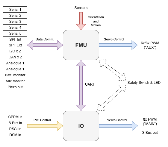
일부 Pixhawk 시리즈 컨트롤러는 공간이나 복잡성을 줄이기 위하여 특정 보드 의 기능 향상을 위하여 I/O 보드 없이 제작됩니다. In this case the I/O driver is not started.
INFO
Manufacturer flight controller variants without an I/O board are often named as a "diminutive" of a version that includes the I/O board: e.g. Pixhawk 4 Mini, _CUAV v5 nano.
Build targets that must run on flight controllers with an I/O board map the FMU outputs to AUX and the I/0 outputs to MAIN (see diagram above). If the target is run on hardware where I/O board is not present or has been disabled, the PWM MAIN outputs will not be present. You might see this, for example, by running px4_fmu-v5_default on Pixhawk 4 (with IO) and Pixhawk 4 Mini (without I/O).
WARNING
On Pixhawk 4 Mini this results in a mismatch between the MAIN label screenprinted on the flight controller and the AUX bus shown during Actuator Configuration.
that if a build target is only ever intended to run on a flight controller that does not have an I/0 board, then the FMU outputs are mapped to MAIN (for example, the px4_fmu-v4_default target for Pixracer).
PX4 PWM outputs are mapped to either MAIN or AUX ports in Actuator Configuration.