액추에이터 설정 및 테스트
PX4 v1.14The Actuators Setup view is used to customize the specific geometry of the vehicle, assign actuators and motors to flight controller outputs, and test the actuator and motor response.
개요
Open the view in QGroundControl here: "Q" (app menu) > Vehicle Setup > Actuators (tab). The displayed elements depend on the selected frame, with outputs mapped by default as shown in the Airframe Reference.
The view has three sections:
- Geometry: Configure the geometry for the selected airframe. This includes number, position and properties of motors and also the number and properties of control surfaces and motor tilt servos.
- Actuator Outputs: Assign motors, control surfaces, and other actuators to specific output.
- Actuator Testing: Test that motors and actuators move in the direction / speed as expected.
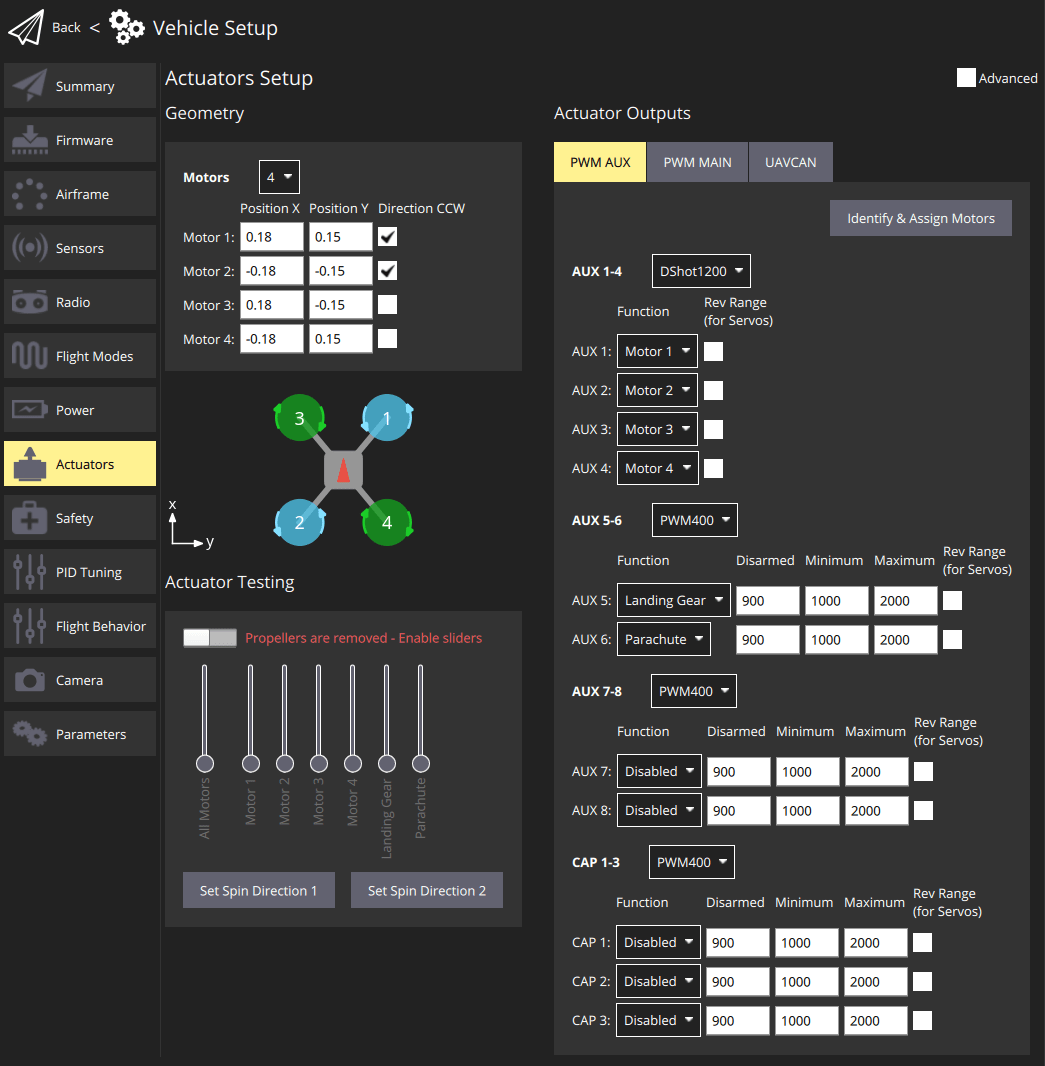
A quadcopter might have an setup screen similar to the one shown below. This defines a 4-rotor copter with X-geometry. It maps the 4 motors to the AUX1 to AUX4 outputs, and specifies that the connect to DShot1200 ESC. It also maps PWM400 AUX outputs for controlling a parachute and landing gear.
INFO
Only the most common settings are displayed by default. Select the Advanced checkbox in the top right corner to display all settings.
지오메트리
The geometry section is used to set any configurable geometry-related parameters for the selected airframe. This includes the number and position of motors, and the number, function, and properties of control surfaces. For VTOL tiltrotor vehicles, it will also include the number and properties of tilt servos
INFO
The UI is customised for the selected airframe:
- Only configurable fields for the selected airframe type are displayed; fields that aren't configurable for the airframe are hidden.
- 모터 위치 다이어그램은 현재 멀티콥터 프레임에만 표시됩니다.
모터 지오메트리
The motor geometry section lets you set the number of motors, the relative position, and other properties of each motor.
멀티콥터 기체의 기하학적 구성은 각 모터의 상대적 x,y 위치를 보여주는 다이어그램을 제공합니다. 다른 프레임의 모터 위치에 대한 광범위한 이해는 기체 참조를 참고하십시오. For example, Tilted-by and axis are only relevant for Tiltrotor VTOL and Standard VTOL vehicles, respectively.
The geometry configuration for multicopter airframes provides a diagram showing the relative x,y positions for each of the motors. See the Airframe Reference for an broad understanding of the motor positions for other frames.
Core geometry concepts and the configuration for a number of different frames are provided in the following sections.
모터 지오메트리: 멀티콥터
The image below shows the geometry setup for a quadrotor multicopter frame with and without advanced settings.
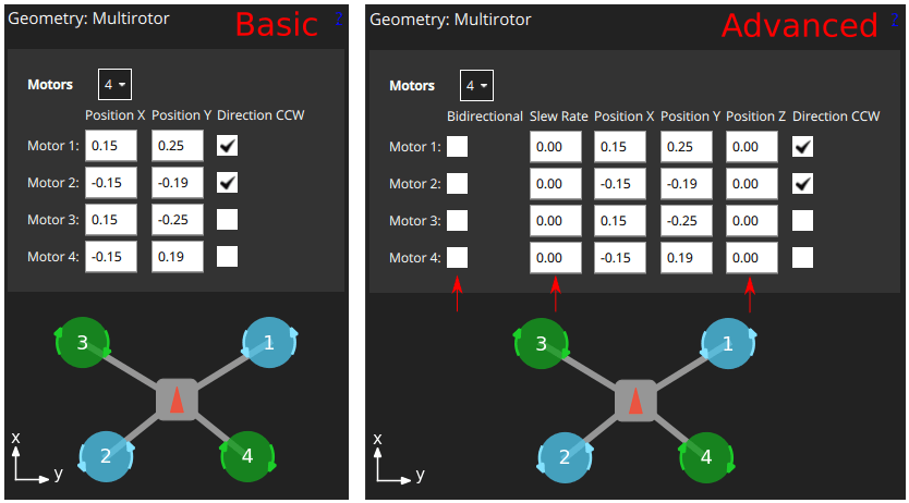
First, the Motors drop-down setting lets you choose the number of motors (4 for the example above).
For each motor you can then set:
Position X: X-position, in metres.Position Y: Y-position, in metres.Position Z: Z-position, in metres.- (Advanced)
Direction CCW: Checkbox to indicate motor spins counter-clockwise (uncheck for clockwise). - (Advanced)
Bidirectional: Checkbox to indicate motor is bidirectional - (Advanced)
Slew Rate: Sets minimum time that the motor output can take to reach its maximum value. Refer to the Control Surfaces Geometry section for more information
INFO
The X, Y, Z positions are in FRD coordinate frame, relative to the centre of gravity. Note, this may not be the same as the position of the flight controller!
모터 지오메트리: VTOL Quadrotor Tailsitter
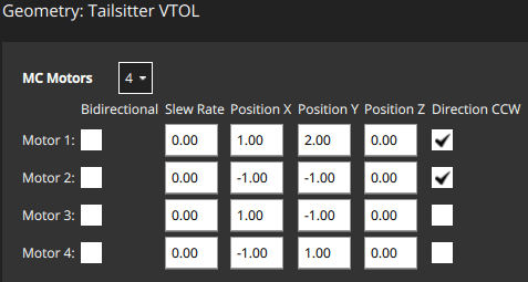
The motor geometry for a VTOL Quad Tailsitter is shown below (the approach for configuring other tailsitter VTOL vehicles will be similar).
Motors have the same configuration fields as for the multicopter geometry.
모터 지오메트리: VTOL 틸트로터
The motor geometry for a Generic Quadplane VTOL Tiltrotor is shown below (the approach for configuring other VTOL tiltrotors will be similar).
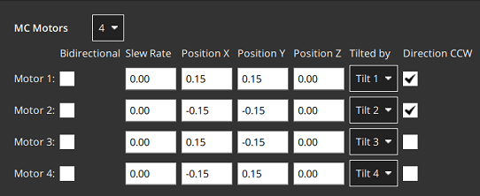
Tilted by: The associated servo used for tilting the motor. The properties of this servo are defined in the Motor Tilt Servo Geometry.
모터 형상: 표준 VTOL
The motor geometry for a Generic Standard VTOL is shown below (the approach for configuring other "Standard VTOL" will be similar).
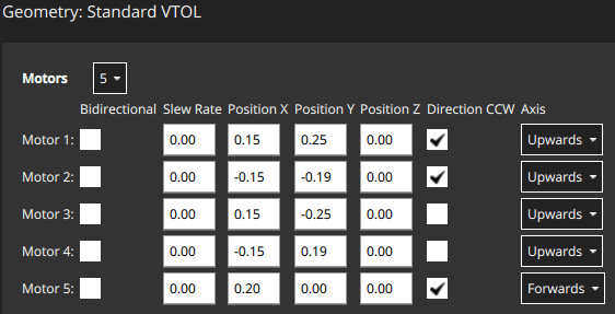
Motors have most of the same configuration fields as for the multicopter geometry. 다시 한 번 이러한 모터는 일반적으로 위에 표시된 것과 같은 종류의 속성을 가집니다.
Axis: One ofUpwards,Downwards,Forwards,Backwards,Leftwards,Rightwards,Custom- If
Customis selected, then the UI displays three additional fields for setting the motor orientation.
- If
모터 지오메트리: 기타 기체
Other vehicle types will define an appropriate motor geometry for their frame type. Once again these motors will generally have the same kinds of properties as shown above.
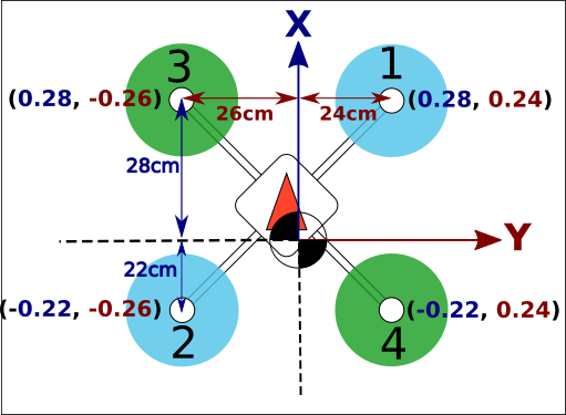
모터 위치를 나타내는 좌표계는 FRD(몸체 프레임 내)이며, 여기서 X축은 앞쪽, Y축은 오른쪽, Z축은 아래쪽을 가르킵니다.
모터 위치 좌표계
The coordinate system for motor positions is FRD (in body frame), where the X axis points forward, the Y axis to the right and the Z axis down.
The origin is the vehicle's centre-of-gravity (COG). This may NOT be the same position as the location of the autopilot.
양방향 모터
Some vehicles may use bidirectional motors (i.e. motors that support spinning in both directions). For example, ground vehicles that want to move forwards and backwards, or VTOL vehicles that have pusher motors that can turn in either direction.
If bidiectional motors are used, make sure to select the Reversible checkbox for those motors (the checkbox is displayed as an "advanced" option).
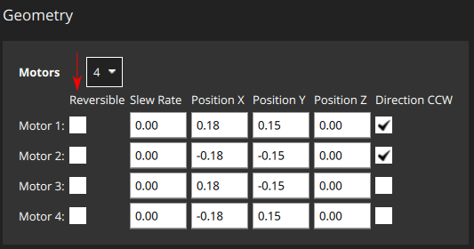
Note that you will need to also ensure that the ESC associated with bidirectional motors is configured appropriately (e.g. 3D mode enabled for DShot ESCs, which can be achieved via DShot commands).
조종면 지오메트리
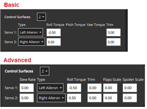
The control surfaces section of the geometry panel lets you set the number and types of control surfaces that are present on the vehicle. You may also need to set trim and slew rate values in some cases. More advanced users can also configure the roll scale, yaw scale, and pitch scale (generally the defaults are acceptable, and this is not needed). An "example" control surface section for a vehicle with two ailerons is shown below. Note that ailerons only affect roll, so the pitch and yaw fields are disabled.
INFO
Only the most common settings are displayed by default. Select the Advanced checkbox in the top right corner of the view to display all settings.
The fields are:
Control Surfaces: The number of control surfaces (set this first!)Type: The type of each control surface:LeftAileron,RightAileron,Elevator,Rudder,Left Elevon,Right Elevon,Left V-Tail,Right V-Tail,Left Flap,Right Flap,Airbrakes,Custom.Roll Torque: Effectiveness of actuator around roll axis (normalised: -1 to 1). Generally you should use the default actuator value.Pitch Torque: Effectiveness of actuator around pitch axis (normalised: -1 to 1). Generally you should use the default actuator value.Yaw Torque: Effectiveness of actuator around yaw axis (normalised: -1 to 1). Generally you should use the default actuator value.Trim: An offset added to the actuator so that it is centered without input. 이것은 시행착오를 거쳐 결정될 수 있습니다. Prefer using the improvedPWM_CENTinstead: PWM control surfaces.- (Advanced)
Slew Rate: Limits the minimum time in which the motor/servo signal is allowed to pass through its full output range, in seconds.- The setting limits the rate of change of an actuator (if not specified then no rate limit is applied). It is intended for actuators that may be damaged or cause flight disturbance if they move too fast — such as the tilting actuators on a tiltrotor VTOL vehicle, or fast moving flaps, respectively.
- For example, a setting of 2.0 means that the motor/servo will not be commanded to move from 0 to 1 at a rate that completes the operation in less than 2 seconds (in case of reversible motors, the range is -1 to 1).
- (Advanced)
Flap Scale: How much this actuator is deflected at the "full flaps configuration" [0, 1] (see Flap Scale and Spoiler Scale Configuration below). Can be used to configure aerodynamic surface as flap or to compensate for generated torque through main flaps. - (Advanced)
Spoiler Scale: How much this actuator is deflected at the "full spoiler configuration" [0, 1] (see Flap Scale and Spoiler Scale Configuration below). Can be used to configure aerodynamic surface as spoiler or to compensate for generated torque through main spoiler. - (VTOL only)
Lock control surfaces in hover:Enabled: Most vehicles do not use control surfaces in hover. 이 설정을 사용하여 기체 역학에 영향을 미치지 않도록 잠그십시오.Disabled: Set this for vehicles that use control surfaces in hover, such as the duo tailsitter (which uses elevons for pitch and yaw control). 또한 조종면을 사용하여 고속으로 이동할 때 호버 모드에서 추가 안정화를 제공하거나 강한 바람이 부는 기체에 대하여 설정합니다.
Flap Scale and Spoiler Scale Configuration
"Flap-control" and "Spoiler-control" are aerodynamic configurations that can either be commanded manually by the pilot (using RC, say), or are set automatically by the controller. For example, a pilot or the landing system might engage "Spoiler-control" in order to reduce the airspeed before landing.
The configurations are an abstract way for the controller to tell the allocator how much it should adjust the aerodynamic properties of the wings relative to the "full flaps" or "full spoiler" configuration (between [0,1], where "1" indicates the full range). The allocator then uses any of the available control surfaces it wants in order to achieve the requested configuration: usually flaps, ailerons, and elevator.
The flap scale and spoiler scale settings in the actuator UI inform the allocator how much ailerons, elevators, flaps, spoilers, and other control surfaces, contribute to a requested "Flap-control" and/or "Spoiler-control" value. Specifically, they indicate how much each control surface should be deflected when the controller is demanding "full flaps" or "full spoiler".
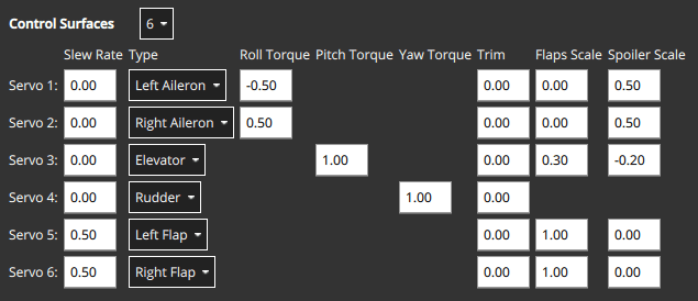
In the following example, the vehicle has two ailerons, one elevator, one rudder and two flaps as control surfaces:
- The flaps have both
Flap Scaleset to 1, meaning that they will be fully deflected with the flap-control at 1. They also have a slew rate of 0.5/s, meaning that it will take 2s to fully deflect them (a slew rate on the flaps is generally recommended to reduce the disturbances their movement creates). - The ailerons are primarily tasked to provide the commanded roll torque. They also have
Spoiler Scaleset to 0.5, and will additionally be deflected upwards 50% if the controller demands full spoiler configuration. The aileron deflection is thus the sum of the (asymmetrical) deflection for the roll torque, plus the (symmetrical) deflection for the spoiler setpoint. - The elevator is primarily tasked to provide pitch torque. It also has non-zero entries in the
Flap ScaleandSpoiler Scalefields. These are the elevator deflections added to compensate for the pitching moments generated by the flaps and spoiler actuators. In the case here the elevator would be deflected 0.3 up when the flaps are fully deployed to counteract the pitching down moment caused by the flaps.
액추에이터 롤, 피치 및 요 스케일링
INFO
For the majority of airframe setups the default values for each control surface types should not be changed.
The Roll scale, Pitch scale and Yaw scale values indicate the normalized effectiveness of the actuator around the corresponding axis.
Tuning the values is a low/level/advanced topic, and is generally only needed when tuning coupled control surfaces (like an elevon, that controls both pitch and roll). In this case the things you need to know are:
- 입력된 숫자는 할당 매트릭스에 직접 입력되며, 원하는 순간(정규화)에서 제어 신호를 얻기 위해 반전됩니다.
- Increasing the scale will reduce the deflection of the control surfaces (as it gets inverted).
조종면 처짐 규칙
Control surfaces that move in either direction from neutral include: Ailerons, Elevons, V-Tails, A-Tails, Rudder.
In order to ensure that these control surfaces always move as expected for positive or negative inputs from the controllers, there needs to be a definition of the deflection directions that is independent of the physical servo setup.
Positive input causes positive deflection. The diagram below shows the direction of movement for positive input:
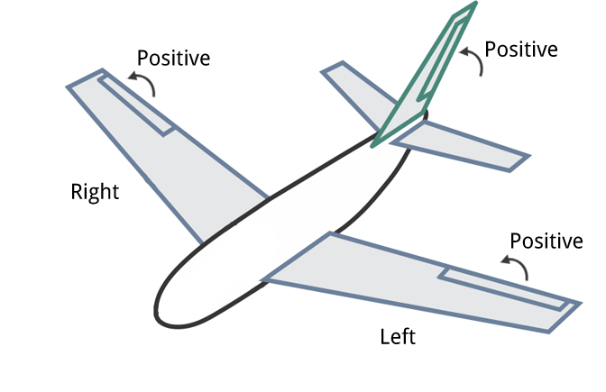
In summary, positive inputs result in:
- Horizontal Control Surfaces: Upwards movement. Includes ailerons and elevons.
- Vertical Control Surfaces: Rightwards movement. Includes rudders.
- Mixed Control Surfaces: Upwards/rightwards movement. Includes V-Tail. A-Tail
TIP
Control surfaces that can only deflect in one direction from the neutral point include: Airbrakes, Spoiler, and Flaps.
For these controls a positive input is always deflection from the neutral (0: no effect, 1: full effect), irrespective of the direction that the control itself moves. They do not respond to negative input.
모터 틸트 서보 지오메트리
VTOL tiltrotor vehicles can tilt their motors to transition between hover and forward flight. This section defines the properties of the tilting servos. These are mapped to specific motors in the motor geometry for a tiltrotor.
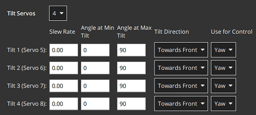
The example below shows the tilt servo setup for the tiltrotor motor geometry shown above.
The values that can be set are:
Tilt servos: The number of servos (tiltable motors).Angle at min tilt: Maximum tilt angle in degrees, relative to the z axis.Angle at max tilt: Minimum tilt angle in degrees, relative to the z-axis.Tilt direction:Towards front(positive x direction) orTowards right(positive y direction).Use for control: Tilt servo used for yaw/pitchNone: Torque control is not used.Yaw: Tilt servos used to control yaw.Pitch: Tilt servos used to control pitch.Both Yaw and Pitch: Tilt servos are used to control both yaw and pitch.
틸트 서보 좌표계
The coordinate system for tilt rotor angles is shown below. The reference direction for tilt angles is straight upwards (0 degrees). Tilt angles towards the front or right of the vehicle are positive, and towards the back or to the left are negative.
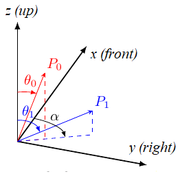
The Angle at min tilt and Angle at max tilt indicate the range of movement for the tilt servo. The minimum tilt is the smaller numerical value (not absolute) of the two angles.
If the max/min tilt vectors are P0 and P1 as shown above, both tilt angles are positive but θ0 is smaller:
Angle at min tilt= θ0Angle at max tilt= θ1
INFO
If the diagram was mirrored so that P0 and P1 were tilting into the -x, -y quadrant, then both the tilt angles would be negative. Because θ1 would more negative (smaller) than θ0, it would be the Angle at min tilt.
Similarly, a servo that moves:
- between the upright and forward positions would have
min=0andmax=90. - symmetrically 45 degrees around the upright position would have
min=-45andmax=45 - between the upright and backward positions would have
min=-90andmax=0.
The Tilt direction indicates whether the servo tilts in the plane towards the Front or Right of the vehicle. On the diagram this would be represented by α that can only take values of 0 (front) or 90 (right).
요/피치 제어용 틸트 서보
이 기능의 사용 여부는 제어에 사용에서 설정합니다.
- Yaw는 일반적으로 이러한 방식으로 설정되지만 모터는 4개 이상의 모터가 있는 기체에서 대신 사용되는 경우가 많습니다.
- 피치는 일반적으로 차동 모터 추력을 사용하여 제어합니다. Control using tilt servos is useful on airframes that can't use differential thrust, such as a Bicopter.
Whether this feature is used is configured in the Use for control setting.
액추에이터 출력
The Actuator Outputs section is used to assign motors, control surface servos, and other actuators used by the particular frame to the physical outputs on the flight controller, and to set parameters for those outputs.
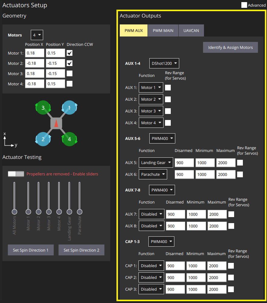
Separate tabs are displayed for each output bus supported by the connected flight controller: PWM MAIN (I/O Board output), PWM AUX (FMU Board output), UAVCAN.
Motors and actuators (which are referred to as "functions") can be assigned to any physical output on any of the available buses.
INFO
PWM AUX outputs are preferred over the PWM MAIN outputs for controlling motors (they have lower latency).
PWM AUX 탭에는 일반적으로 카메라 캡처/트리거 입력으로 사용되는 CAP 출력이 있습니다. 그러나, CAP 출력을 다른 출력 기능에 매핑할 수 있으며 다른 AUX 출력을 카메라 캡처/트리거 입력으로 사용 가능합니다. Therefore it is not possible to map Servo and a Motor in the same output group, as they usually operate at a different rate.
The PWM AUX tab has CAP outputs that are generally used as the camera capture/trigger input. However you can map the CAP outputs to other output functions, and other AUX outputs can be used as camera capture/triggering input.
INFO
Configuring the Camera Capture / Trigger input requires a reboot to take effect
You should assign functions to the outputs that match your physical wiring of motors and servos, and use the Actuator Testing section described below to determine appropriate output parameter values. These steps are covered in Output Assignment and Configuration.
Output Functions
Output functions are used to map the "logical functions" of an airframe, such as Motor 1 or Landing gear, to physical outputs like FMU output pin 2. This makes it easy to use a particular output pin for almost any purpose.
Some functions are only relevant to particular frames or output types, and will not be offered on others.
Functions include:
Disabled: Output has no assigned function.Constant_Min: Output set to constant minimum value (-1).Constant_Max: Output is set to constant maximum value (+1).Motor 1toMotor 12: Output is indicated motor. Only motors allowed for airframe are displayed.Servo 1toServo 8: Servo output. These are further assigned a specific meaning based on airframe, such as "tilt servo", "left aileron".Peripheral via Acutator Set 1toPeripheral via Acutator Set 6: Generic Actuator Control with MAVLink.Landing Gear: Output is landing gear.Parachute: Output is parachute. The minimum value is sent in normal use and the maximum value is emitted when a failsafe is triggered.RC Roll: Output is passthrough roll from RC (RC_MAP_ROLL maps an RC channel to this output).RC Pitch: Output is passthrough pitch from RC (RC_MAP_PITCH maps an RC channel to this output).RC Throttle: Output is passthrough throttle from RC (RC_MAP_THROTTLE maps an RC channel to this output).RC Yaw: Output is yaw from RC (RC_MAP_YAW maps an RC channel to this output).RC Flaps: Output is flaps from RC (RC_MAP_FLAPS maps an RC channel to this output).RC AUXntoRC AUX1: Outputs used for arbitrary payloads triggered by RC passthrough.Gimbal Roll: Output controls gimbal roll.Gimbal Pitch: Output controls Gimbal pitch.Gimbal Yaw: Output controls Gimbal yaw.GripperPX4 v1.14: Output controls gripper open/close.Landing_Gear_WheelPX4 v1.14: Output controls deployment of landing gear wheel
The following functions can only be applied to FMU outputs:
Camera_Trigger: Output to trigger camera. Enabled whenTRIG_MODE==0. Configured viaTRIG_*parameters.Camera_Capture: Input to get image capture notification. Enabled when CAM_CAP_FBACK==0. Configured viaCAM_CAP_*parameters.PPS_Input: Pulse-per-second input capture. Used for GPS synchronisation. Enabled whenPPS_CAP_ENABLE==0
INFO
The functions are defined in source at /src/lib/mixer_module/output_functions.yaml. This list is correct at PX4 v1.15.
액추에이터 테스트
The Actuator Testing section in lower-right corner provides sliders that can be used to test (and determine) actuator and motor settings. A slider is provided for each output defined in the Actuator Outputs section. The slider example below shows the section for a typical VTOL Tiltrotor airframe.
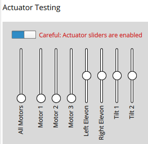
The section has an Enable Sliders switch that must be toggled before sliders can be used. 이것은 스위치가 활성화된 후 갑작스러운 모터 움직임을 방지하기 위한 안전 장치입니다.
INFO
After you toggle the Enable sliders switch, actuators/motors won't do anything until the corresponding slider is moved. This is a safety feature to prevent sudden motor movements after switch is enabled.
Sliders can be used to verify the following:
- Actuators (Motors, Control surfaces, etc.) are assigned to the expected output.
- Motors don't spin when at the
disarmedPWM output value - Motors barely spin at the
minimumPWM output value. - Motors give positive thrust in the expected direction
- Control Surfaces are in the correct idle position for
disarmedoutput value - Control Surfaces move in the direction as defined in the Control Surface Convention
- Motor Tilt Servos are in the correct idle position for
disarmedoutput value - Motor Tilt Servos move in the direction as defined in the Tilt Servo Convention
출력 할당 및 설정
Outputs are assigned to functions and configured in the Actuator Outputs section, while the Actuator Testing sliders are commonly used to determine appropriate configuration values to enter:
- MC vehicles that have connected motors to PWM outputs can use the Identify & Assign Motors button to perform motor assignment "semi-automatically".
- Output assignment of both motors and actuators can be done/checked using sliders (see Output Assignment (Manual)).
- 모든 출력에 대한 해제, 최소 및 최대 설정도 슬라이더를 사용하여 결정할 수 있습니다. This is shown as part of Motor Configuration, Control Surface Setup, Tilt servo setup
멀티콥터 PWM: 모터 할당
You can use the Identify & Assign Motors button to assign motors to PWM outputs using a semi-automated process.
INFO
This is the easiest way to assign motors, but is currently only supported for motors on multicopter vehicles that are connected to PWM outputs (UAVCAN outputs and other frame types do not support this feature). On other frames you can follow the instructions in Output Assignment (Manual).
WARNING
Remove the propellers from motors before assigning outputs or any testing.
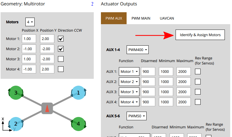
When you click the button, QGC sends a command to a motor, causing it to spin. To assign that motor to an output you simply select the corresponding motor displayed in the screen. QGC will then spin the next motor for you to assign, and so on.
Instructions:
프레임의 모터와 일치하도록 모터 형상을 설정합니다.
모터를 할당할 PWM 탭을 선택합니다.
Click the Identify & Assign Motors button.
One motor will start spinning (click Spin Motor Again if it stops spinning too quickly to note.)
지오메트리 섹션에서 해당 모터를 선택합니다.
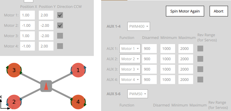
모든 모터를 할당한 후 도구는 출력에 대한 올바른 모터 매핑을 설정한 다음 종료됩니다.
출력 할당(수동)
WARNING
Remove the propellers from motors before assigning outputs or any testing.
Actuator outputs for both motors and servos can be manually assigned using sliders in the Actuator Testing section.
To assign an actuator:
- First assign functions to the outputs that you think are likely to be correct in the Actuator Outputs section.
- Toggle the Enable sliders switch in Actuator Testing section.
- 테스트하려는 액추에이터의 슬라이더를 이동합니다.
- 모터는 최소 추력 위치로 이동하여야 합니다.
- 서보는 중간 위치 근처로 이동하여야 합니다.
- 어떤 액츄에이터가 차량에서 움직이는 지 확인하십시오. This should match the actuator positions for your geometry (the airframe reference shows motor positions for a number of standard airframes).
- 올바른 액츄에이터가 움직이면 다음 단계로 진행합니다.
- 잘못된 액츄에이터가 움직이면 출력 할당을 변경합니다.
- 아무 것도 움직이지 않으면, 슬라이더를 범위 중간에 늘리고 필요한 경우 더 높입니다. 그 후 아무 것도 움직이지 않으면, 출력이 연결되지 않거나 모터에 전원이 공급되지 않거나 출력 설정에 오류가 있을 수 있습니다. 문제를 해결하여야 합니다("무엇이든"이 움직이는지 확인하기 위하여 다른 액추에이터 출력을 시도할 수 있음).
- 슬라이더를 "무장 해제" 위치로 되돌립니다(모터의 경우 슬라이더 하단, 서보의 경우 슬라이더 중앙).
- 모든 액추에이터에 대하여 반복합니다.
모터 설정
INFO
If using PWM or OneShot ESCs, you should first perform ESC Calibration (this topic also covers PWM specific motor configuration).
DShot ESCs do not require configuration of the command limits but only rotation direction.
WARNING
Remove propellers!
각각의 모터에 대하여:
- don't spin when disarmed (at the
disarmedPWM output value). - barely but reliably spin up at the
minimumPWM output value. - have the lowest
maximumPWM output value that spins the motor at its highest rate. - give positive thrust in the expected direction.
For each motor:
모터 슬라이더를 아래로 당겨서 아래쪽에 찰칵 소리가 나도록 합니다. In this position the motor is set to the outputs
disarmedvalue.- 모터가 이 위치에서 회전하지 않는 지 확인하십시오.
- If the motor spins, reduce the corresponding PWM
disarmedvalue in the Actuator Outputs section to below the level at which it still spins.
Slowly move the slider up until it snaps to the minimum position. In this position the motor is set to the outputs
minimumvalue.이 위치에서 모터가 매우 느리게 회전하는 지 확인합니다.
If the motor is not spinning, or spinning too fast you will need to adjust the corresponding PWM
minimumvalue in the Actuator Outputs such that the motors barely spin.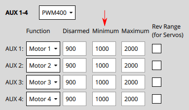
INFO
For DShot output, this is not required.
:::
Increase the slider value to a level where you can verify that the motor is spinning in the correct direction and that it would give a positive thrust in the expected direction.
- The expected thrust direction can vary by vehicle type. For example in multicopters the thrust should always point upwards, while in a fixed-wing vehicle the thrust will push the vehicle forwards.
- For VTOL, thrust should point upwards when the Tilt Servo is at 0 degrees as defined the Tilt Servo Convention. Testing of the Tilt Servo is covered below as well.
- If thrust is in the wrong direction, you may need to reverse the motors.
Increase the slider value to the maximum value, so the motor is spinning quickly. Reduce the value of the PWM output's
maximumvalue just below the default. Listen to the tone of the motors as you increase the value in small (25us) increments. The "optimal" maximum value is the value at which you last hear a change in the tone.
조종면 설정
First set the frame rate for the servos used in each group of outputs. This would normally be set to the maximum value supported by your servo. Below we show how you would set it to PWM50 (the most common value).

INFO
You will almost certainly need to change the pulse rate from the default of 400Hz because support is rare (if not supported the servo will usually make an "odd" noise). If you're using PWM servos, PWM50 is far more common. If a high rate servo is really needed, DShot offers better value.
PWM: Control surfaces that move both directions about a neutral point
To facilitate setting the neutral point of the servos, a bilinear curve function can be defined using the following parameters PWM_MAIN_CENTx / PWM_AUX_CENTx for each servo. This allows for unequal deflections in the positive and negative direction:
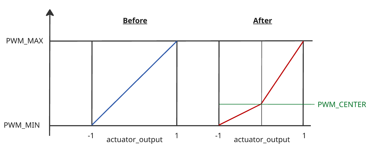
To set this up:
Set all surface
Trimto0.00for all surfaces: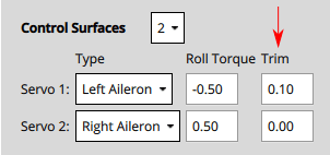
Set the
PWM_MAIN_CENTx/PWM_AUX_CENTxvalue so that the surface will stay at the neutral (aligned with airfoil) position. This is usually around1500for PWM servos (near the center of the servo range).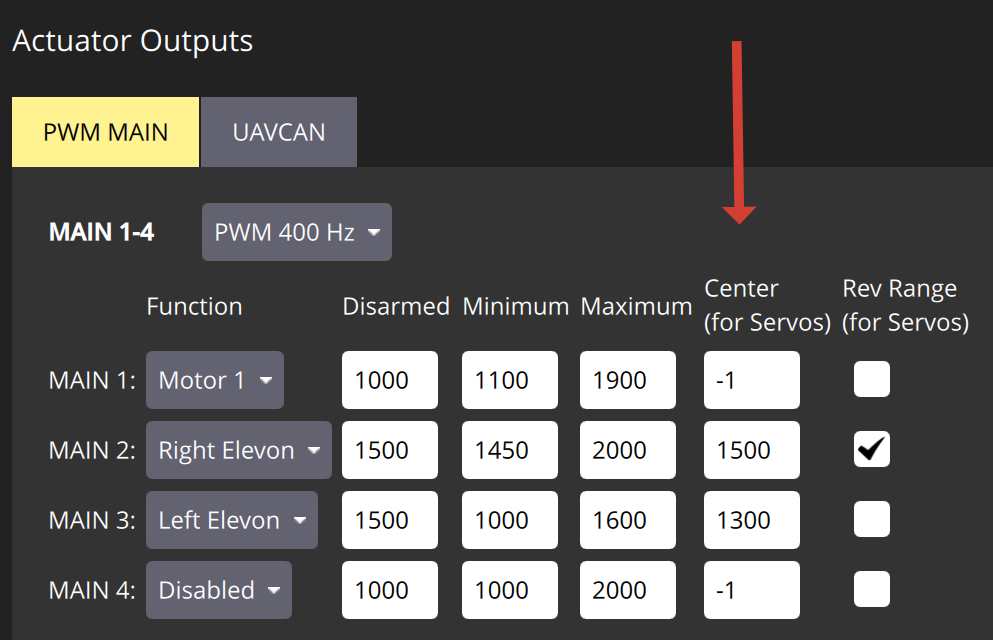
Gradually increase the
Maximumfor each servo until the desired deflection is reached. Check the deflection with a remote manual mode whileCOM_PREARM_MODEis set toAlwaysor use the sliders.Gradually decrease the
Minimumfor each servo, until the desired deflection is reached.Set
Disarmedvalue to the desired value. It is usually desirable to have it the same as theCentervalue.
INFO
If you want to retain the linear behaviour of the servo after setting the Center, make sure to adjust the Minimum or Maximum, such that both intervals (min to cent & cent to max) are equally large.
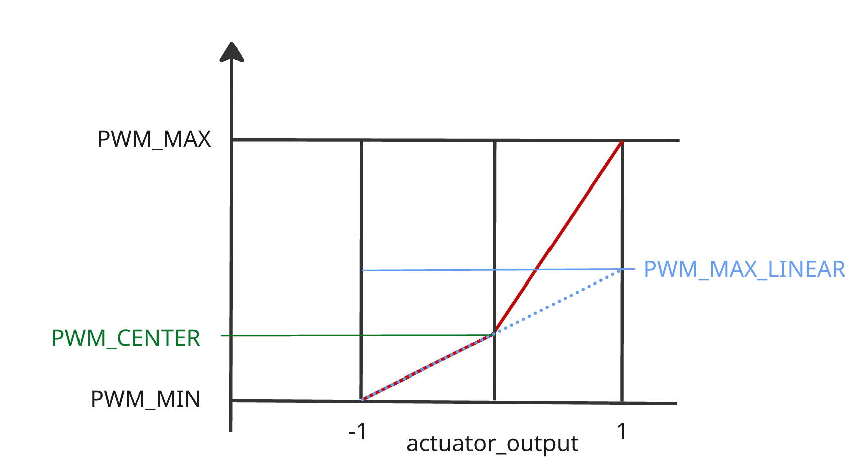
Non-PWM: Control surfaces that move both directions about a neutral point
Control surfaces that move either direction around a neutral point include: ailerons, elevons, V-tails, A-tails, and rudders.
To set these up:
Set all
PWM_MAIN_CENTxandPWM_AUX_CENTxto default (-1), or trimming will not be possible.Set the
Disarmedvalue so that the surfaces will stay at neutral position when disarmed. This is usually around1500for PWM servos (near the centre of the servo range).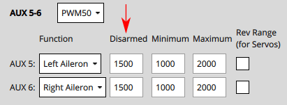
Move the slider for the surface upwards (positive command) and verify that it moves in the direction defined in the Control Surface Convention.
- Ailerons, elevons, V-Tails, A-Tails, and other horizontal surfaces should move up.
- Rudders and other "purely vertical" surfaces should move right.
TIP
It is important that the slider movement matches the control surface convention, in order to normalize control for different servo mountings (moving the slider up may actually decrease the output value sent to the servo).
:::
If the control surface moves in the opposite direction, click on the Rev Range checkbox to reverse the range.
Move the slider again to the middle and check if the Control Surfaces are aligned in the neutral position of the wing.
- If it is not aligned, you can set the Trim value for the control surface.
INFO
This is done in the
Trimsetting of the Geometry panel, usually by "trial and error".
:::
- After setting the trim for a control surface, move its slider away from the centre, release, and then back into disarmed (middle) position. Confirm that surface is in the neutral position.
TIP
If any servo has a PWM_MAIN_CENTx or PWM_AUX_CENTx not set to default (-1), the system will automatically remove Trim from all surfaces. This is done to prevent mixing of old and new trimming tools.
INFO
Another way to test without using the sliders would be to set the COM_PREARM_MODE parameter to Always:
- 이렇게 하면 기체가 무장 해제된 경우에도 서보 제어가 가능하며 제어 표면에 트림 설정이 지속적으로 적용됩니다.
- Trim에 대해 다른 값을 설정하고 정렬을 확인한 다음 만족하는 값으로 설정할 수 있습니다.
Control surfaces that move from neutral to full deflection
Control surfaces that move only one direction from neutral include: airbrakes, spoilers, and flaps.
For these controls you should set the minimum and maximum PWM values according to the full range of the control. The Disarmed value should then match the value (of maximum or minimum) that corresponds to control being in the "neutral" position. For a flap, that is when the flap is fully retracted and flush with the wing.
One approach for setting these up is:
- Set all
PWM_MAIN_CENTxandPWM_AUX_CENTxto default (-1), or trimming will not be possible. - Set values
Disarmedto1500,Minto1200,Maxto1700so that the values are around the centre of the servo range. - Move the corresponding slider up and check the control moves and that it is extending (moving away from the disarmed position). If not, click on the
Rev Rangecheckbox to reverse the range. - Enable slider in the disarmed position, them change the value of the
Disarmedsignal until the control is retracted/flush with wing. This may require that theDisarmedvalue is increased or decreased:- If the value was decreased towards
Min, then setMinto matchDisarmed. - If the value was increased towards
Max, then setMaxto matchDisarmed.
- If the value was decreased towards
- The value that you did not set to match
Disarmedcontrols the maximum amount that the control surface can extend. Set the slider to the top of the control, then change the value (MaxorMin) so that the control surface is fully extended when the slider is at top. - (Only PWM servos) Set the
Centervalue to the middle betweenMinandMax.
Special note for flaps
In some vehicle builds, flaps may be configured such that both flaps are controlled from a single output. In this case, you need to ensure that both flaps extend/deploy when raising the corresponding slider. If this is not the case and one servo deploys correctly and one does not, you need to change the servo direction with a third party servo programmer. Alternatively, you might move the servo that is not deflecting in the correct orientation to its own servo output channel and then reverse its direction via the Rev range check box.
틸트 서보 설정
First set the frame rate for the servos used in each group of outputs. This would normally be set to the maximum value supported by your servo. Below it is set to PWM50 (the most common value). Note, this part of the setup is the same as for control surfaces above.
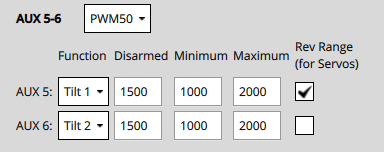
For each of the tilt servos:
Set the
Disarmedvalue (e.g.1000or2000for PWM Servos) so that the servo will be positioned in expected direction when disarmed.Position the slider for the servo in the lowest position, and verify that a positive value increase will point towards the
Angle at Min Tilt(defined in the Geometry section).
Position the slider for the servo in the highest position, and verify that positive motor thrust will point towards the
Angle at Max Tilt(as defined in the Geometry section).
기타 참고 사항
안전 버튼을 쿨러야 액츄에이트를 테스트 할 수 있습니다.
중지 스위치를 사용하면 모터를 즉시 중지할 수 있습니다.
해당 슬라이더가 변경될 때까지 서보는 실제로 이동하지 않습니다.
The parameter COM_MOT_TEST_EN can be used to completely disable actuator testing.
On the shell, actuator_test can be used as well for actuator testing.
VTOLs will automatically turn off motors pointing upwards during fixed-wing flight:
- 표준 VTOL: 멀티콥터 모터로 정의된 모터가 꺼집니다.
- 틸트로터: 연결된 틸트 서보가 없는 모터는 꺼집니다.
- 테이시터는 고정익 비행시에도 모터를 끄지 않습니다.
The following formula can be used to migrate from surface trim to PWM trim:
plainPWM_MAIN_CENTx = ((PWM_MAX - PWM_MIN) / 2) * CA_SV_CSx_TRIM + PWM_MIN + ((PWM_MAX - PWM_MIN) / 2)
모터 역전
The motors must turn in the direction defined in configured geometry ("Direction CCW" checkboxes). If any motors do not turn in the correct direction they must be reversed.
There are several options:
If the ESCs are configured as DShot you can permanently reverse the direction via UI. The Set Spin Direction buttons are displayed below the Actuator sliders (if DShot motors are used). These popup a dialog in which you select the motor for which you want to apply the direction.
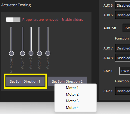
Note that the current direction cannot be queried, so you may need to try both options.
모터 케이블 3개 중 2개를 변경하면됩니다(어떤 케이블이든 상관 없음).
INFO
If motors are not connected via bullet-connectors, re-soldering is required (this is a reason, among others, to prefer DShot ESCs).
:::