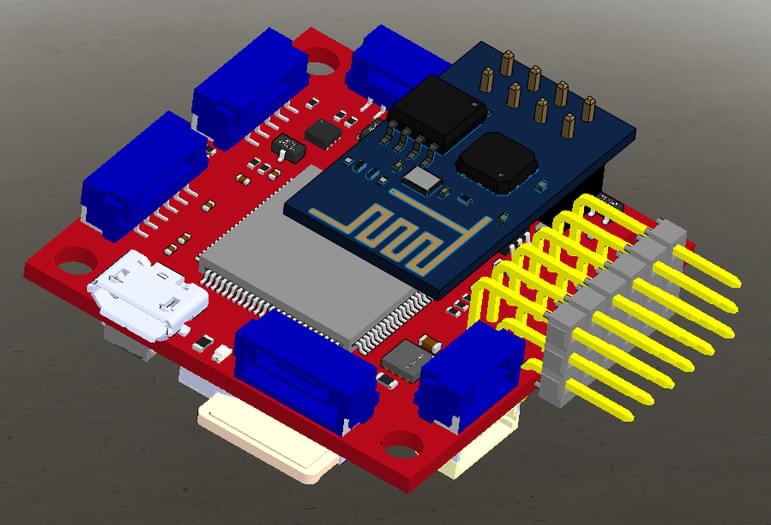
mRo Pixracer
WARNING
PX4 does not manufacture this (or any) autopilot. Contact the manufacturer for hardware support or compliance issues.
Pixhawk® XRacer 보드 제품군은 소형 레이싱 쿼드와 비행기에 최적화되어 있습니다. In contrast to Pixfalcon and Pixhawk it has in-built WiFi, new sensors, convenient full servo headers, CAN and supports 2M flash.

TIP
This autopilot is supported by the PX4 maintenance and test teams.
주요 특징
- Main System-on-Chip: STM32F427VIT6 rev.3
- CPU : 단정밀도 FPU의 180MHz ARM Cortexex® M4
- RAM : 256KB SRAM (L1)
- 표준 FPV 폼 팩터 : 36x36mm, 표준 30.5mm 구멍 패턴
- Invensense® ICM-20608 가속 / 자이로 (4KHz) / MPU9250 가속 / 자이로 / 마그 (4KHz)
- 온도 보상 기능 HMC5983 자력계
- Measurement Specialties MS5611 기압계
- JST GH 커넥터
- microSD (로깅)
- Futaba S.BUS 및 S.BUS2/Spektrum DSM2 및 DSMX/Graupner SUMD/PPM 입력/Yuneec ST24
- FrSky® 텔레메트리 포트
- OneShot PWM 출력(설정 가능)
- 옵션 : 안전 스위치 및 부저
Where to Buy
Pixracer Pro is available from the store.3dr.com.
액세서리에는 아래의 내용물이 포함됩니다.
- Digital airspeed sensor
- Hobbyking® OSD + EU Telemetry (433 MHz) (Discontinued)
키트
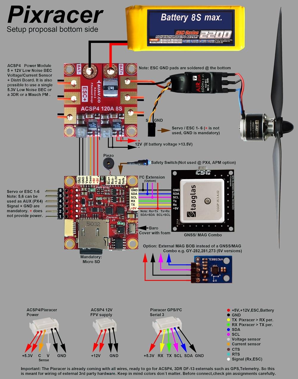
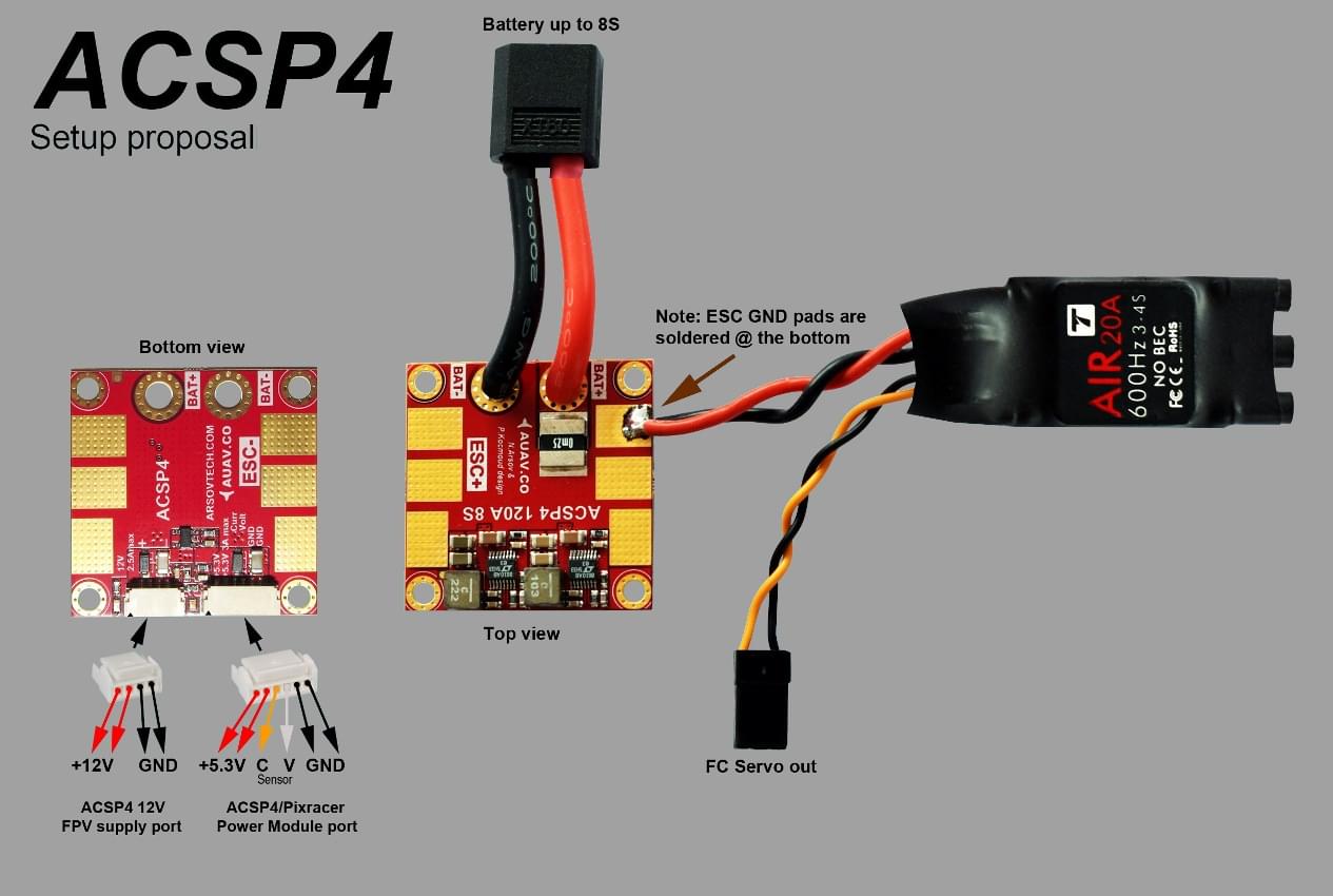
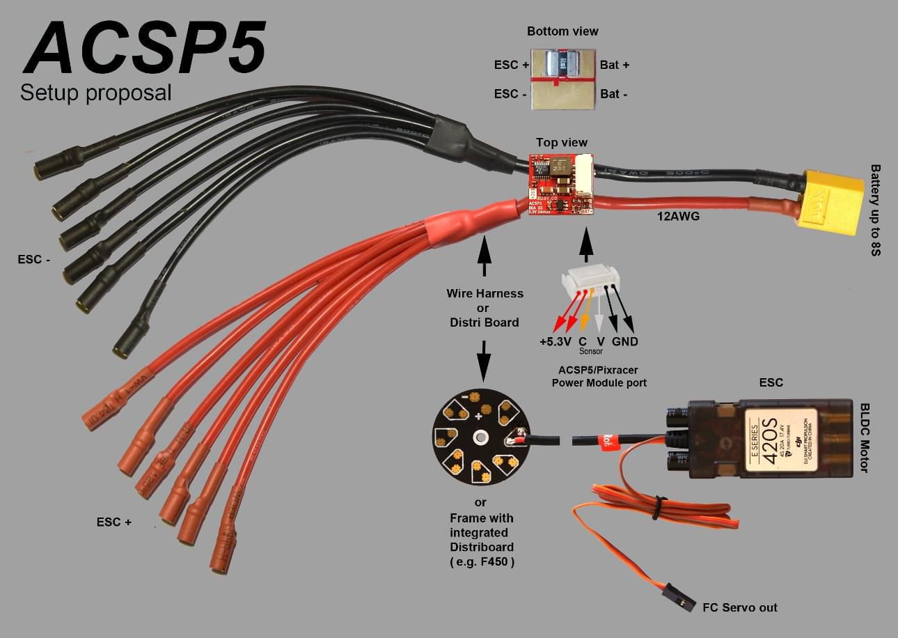
Pixracer는 별도의 항공전자기기 전원공급장치를 사용하도록 설계되었습니다. 이는 모터 또는 ESC의 전류 서지가 비행 컨트롤러로 다시 흐르고 섬세한 센서를 방해하는 것을 방지하는 데 필요합니다.
- 전원 모듈(전압 및 전류 감지 포함)
- I2C 스플리터(AUAV, Hobbyking 및 3DR® 주변 장치 지원)
- 모든 일반 주변기기용 케이블 키트
Wi-Fi(USB 필요 없음)
보드의 주요 기능중 하나는 새 펌웨어, 시스템 설정과 기내 원격 측정을 위해 Wi-Fi를 사용할 수 있는 것입니다. 이를 통해 데스크탑 시스템이 필요없습니다.
INFO
Firmware upgrade is not yet enabled over WiFi (it is supported by the default bootloader but not yet enabled). Setup and telemetry are supported.
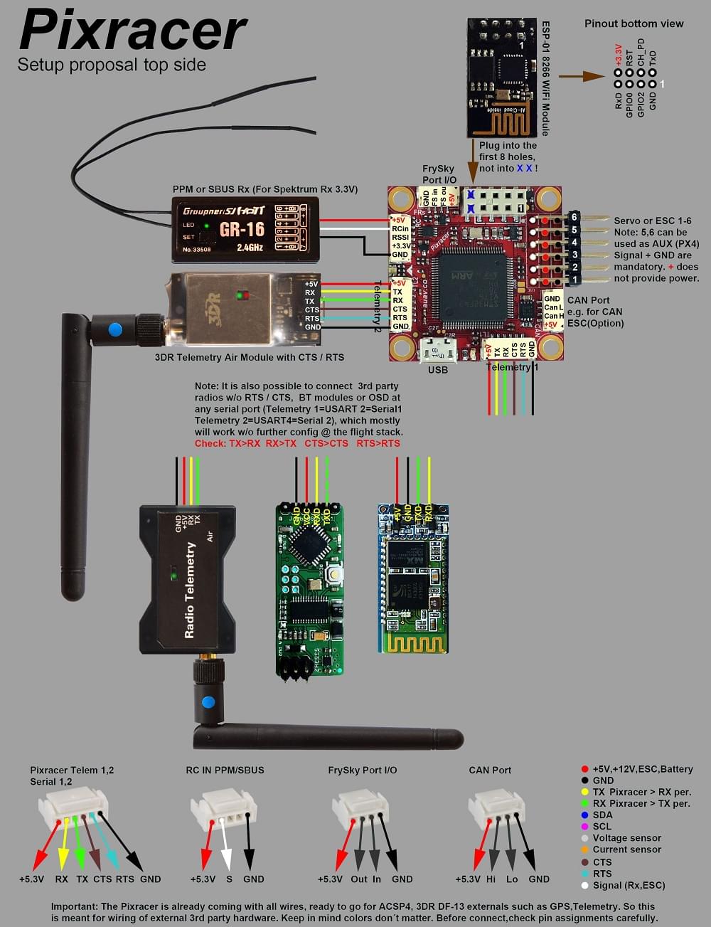
조립
See the Pixracer Wiring Quickstart
Wiring Diagrams
INFO
If using TELEM2 for an external telemetry module you will need to configure it as a MAVLink serial port. For more information see: Pixracer Wiring Quickstart > External Telemetry
커넥터
All connectors follow the Pixhawk connector standard. Unless noted otherwise all connectors are JST GH.
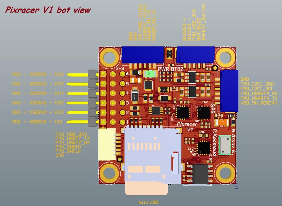
핀배열
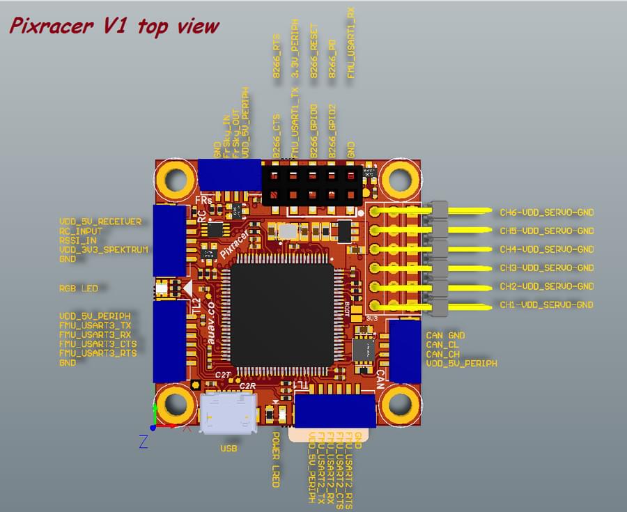
TELEM1, TELEM2+OSD 포트
| 핀 | 신호 | 전압 |
|---|---|---|
| 1(red) | VCC | +5V |
| 2 (흑) | TX (출력) | +3.3V |
| 3 (흑) | RX (입력) | +3.3V |
| 4 (흑) | CTS (입력) | +3.3V |
| 5 (흑) | RTS (출력) | +3.3V |
| 6 (흑) | GND | GND |
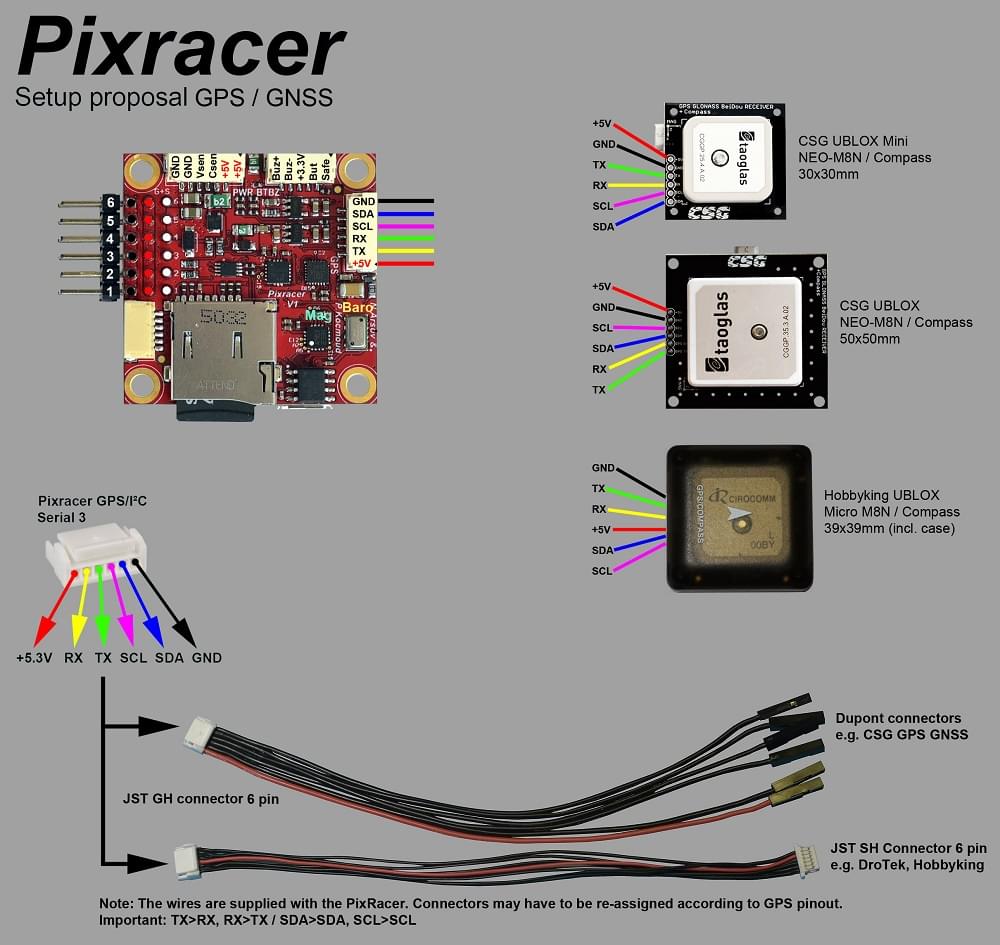
GPS 포트
| 핀 | 신호 | 전압 |
|---|---|---|
| 1(red) | VCC | +5V |
| 2 (흑) | TX (출력) | +3.3V |
| 3 (흑) | RX (입력) | +3.3V |
| 4 (흑) | I2C1 SCL | +3.3V |
| 5 (흑) | I2C1 SDA | +3.3V |
| 6 (흑) | GND | GND |
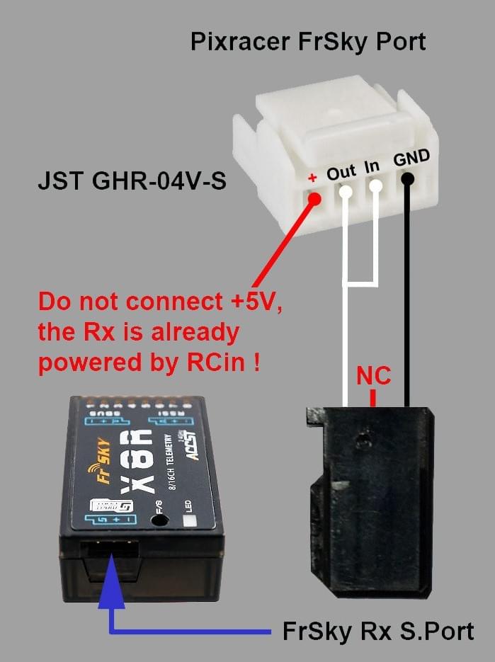
FrSky 텔레메트리/SERIAL4
| 핀 | 신호 | 전압 |
|---|---|---|
| 1(red) | VCC | +5V |
| 2 (흑) | TX (출력) | +3.3V |
| 3 (흑) | RX (입력) | +3.3V |
| 4 (흑) | GND | GND |
RC 입력(PPM/S.BUS/Spektrum/SUMD/ST24 허용)
| 핀 | 신호 | 전압 |
|---|---|---|
| 1(red) | VCC | +5V |
| 2 (흑) | RC IN | +3.3V |
| 3 (흑) | RSSI 입력 | +3.3V |
| 4 (흑) | VDD 3V3 | +3.3V |
| 5 (흑) | GND | GND |
CAN
| 핀 | 신호 | 전압 |
|---|---|---|
| 1(red) | VCC | +5V |
| 2 (흑) | CAN_H | +12V |
| 3 (흑) | CAN_L | +12V |
| 4 (흑) | GND | GND |
전원
| 핀 | 신호 | 전압 |
|---|---|---|
| 1(red) | VCC | +5V |
| 2 (흑) | VCC | +5V |
| 3 (흑) | CURRENT | +3.3V |
| 4 (흑) | VOLTAGE | +3.3V |
| 5 (흑) | GND | GND |
| 6 (흑) | GND | GND |
스위치
| 핀 | 신호 | 전압 |
|---|---|---|
| 1(red) | SAFETY | GND |
| 2 (흑) | !IO_LED_SAFETY | GND |
| 3 (흑) | VCC | +3.3V |
| 4 (흑) | BUZZER- | - |
| 5 (흑) | BUZZER+ | - |
디버그 포트
The pinouts and connector comply with the Pixhawk Debug Mini interface defined in the Pixhawk Connector Standard (JST SM06B connector).
| 핀 | 신호 | 전압 |
|---|---|---|
| 1(red) | VCC TARGET SHIFT | +3.3V |
| 2 (흑) | CONSOLE TX (출력) | +3.3V |
| 3 (흑) | CONSOLE RX (입력) | +3.3V |
| 4 (흑) | SWDIO | +3.3V |
| 5 (흑) | SWCLK | +3.3V |
| 6 (흑) | GND | GND |
For information about using this port see:
- SWD Debug Port
- PX4 System Console (Note, the FMU console maps to UART7).
시리얼 포트 매핑
| UART | 장치 | 포트 |
|---|---|---|
| UART1 | /dev/ttyS0 | WiFi (ESP8266) |
| USART2 | /dev/ttyS1 | TELEM1 (흐름 제어) |
| USART3 | /dev/ttyS2 | TELEM2 (흐름 제어) |
| UART4 | ||
| UART7 | 콘솔 | |
| UART8 | SERIAL4 |
회로도
The reference is provided as: Altium Design Files
The following PDF files are provided for convenience only:
- pixracer-rc12-12-06-2015-1330.pdf
- pixracer-r14.pdf - R14 or RC14 is printed next to the SDCard socket
펌웨어 빌드
TIP
Most users will not need to build this firmware! It is pre-built and automatically installed by QGroundControl when appropriate hardware is connected.
To build PX4 for this target:
make px4_fmu-v4_default설정
Compass calibration should be done with USB disconnected. This is always recommended, but is necessary on Pixracer because the USB connection produces particularly large levels of magnetic interference.
Configuration is otherwise the same as for other boards.
Credits
This design was created by Nick Arsov and Phillip Kocmoud and architected by Lorenz Meier, David Sidrane and Leonard Hall.