CUAV V5+ 자동조종장치
WARNING
PX4 does not manufacture this (or any) autopilot. Contact the manufacturer for hardware support or compliance issues.
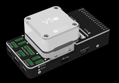
V5+® is an advanced autopilot manufactured by CUAV®. CUAV®와 PX4팀이 공동으로 설계하였습니다.
자동조종장치는 상용시스템 통합에 권장되지만, 학술 연구와 기타 용도에도 적합합니다.

주요 기능은 다음과 같습니다.
- Full compatibility with the Pixhawk project FMUv5 design standard and uses the Pixhawk Connector Standard for all external interfaces.
- 더 안정적이고 신뢰할 수 있는 센서와 함께 FMU v3보다 고급 프로세서, RAM 및 플래시 메모리.
- PX4와 펌웨어 호환.
- 모듈식 설계를 통해 사용자는 자신의 캐리어 보드를 설정할 수 있습니다.
- 고성능 충격흡수 시스템을 갖춘 내장형 진동감쇠 시스템.
- 비행 안전 향상을 위한 다중 센서와 전원 시스템.
INFO
This flight controller is manufacturer supported.
요약
메인 FMU 프로세서: STM32F765
- 32 비트 Arm® Cortex®-M7, 216MHz, 2MB 메모리, 512KB RAM
IO 프로세서: STM32F100
- 32 비트 Arm® Cortex®-M3, 24MHz, 8KB SRAM
내장 센서 :
- 가속도계/자이로스코프 : ICM-20689
- 가속도계/자이로스코프 : BMI055
- 자력계 : IST8310
- 기압계: MS5611
인터페이스:
- PWM 출력 8-14개(IO 6개, FMU 8개)
- FMU의 전용 PWM/캡처 입력 3 개
- CPPM 전용 RC 입력
- 아날로그/PWM RSSI 입력이있는 Spektrum/DSM 및 S.Bus 전용 RC 입력
- 아날로그/PWM RSSI 입력
- PWM Servo 출력
- 범용 시리얼 포트 5개
- I2C 포트 4개
- SPI 버스 4개
- 2 CANBuses with serial ESC
- 배터리 2 개의 전압 및 전류에 대한 아날로그 입력
전원시스템
- 전원: 4.3~5.4V
- USB 입력: 4.75~5.25V
중량과 크기
- 중량: 90g
- Dimensions: 85.5*42*33mm
기타 특성:
- 작동 온도: -20 ~ 80°c (측정 값)
구매처
CUAV Aliexpress (International users)
CUAV Taobao (China Mainland users)
INFO
Autopilot may be purchased with included Neo GPS module
배선
핀배열
Download V5+ pinouts from here.
정격 전압
V5+ AutoPilot supports redundant power supplies - up to three sources may be used: Power1, Power2 and USB. You must supply power to at least one of these sources, or the flight controller will be unpowered.
INFO
On FMUv5 based FMUs with PX4IO module (as is the case for the V5+), the Servo Power Rail is only monitored by the FMU. It is neither powered by, nor provides power to the FMU. However, the pins marked + are all common, and a BEC may be connected to any of the servo pin sets to power the servo power rail.
Normal Operation Maximum Ratings
이러한 조건에서 전원은 아래의 순서대로 시스템에 전원을 공급하여야합니다.
Power1andPower2inputs (4.3V to 5.4V)USBinput (4.75V to 5.25V)
과전류 보호
The V5+ has over current protection on the 5 Volt Peripheral and 5 Volt high power, which limits the current to 2.5A. The V5+ has short circuit protection.
WARNING
Up to 2.5 A can be delivered to the connectors listed as pin 1 (although these are only rated at 1 A).
펌웨어 빌드
TIP
Most users will not need to build this firmware! It is pre-built and automatically installed by QGroundControl when appropriate hardware is connected.
To build PX4 for this target:
make px4_fmu-v5_default디버그 포트
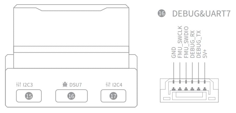
The PX4 System Console and SWD interface operate on the FMU Debug port (DSU7). 보드에는 I/O 디버그 인터페이스가 없습니다.

The debug port (DSU7) uses a JST BM06B connector and has the following pinout:
| 핀 | 신호 | 전압 |
|---|---|---|
| 1(red) | 5V+ | +5V |
| 2 (흑) | DEBUG TX(출력) | +3.3V |
| 3 (흑) | DEBUG TX(입력) | +3.3V |
| 4 (흑) | FMU_SWDIO | +3.3V |
| 5 (흑) | FMU_SWCLK | +3.3V |
| 6 (흑) | GND | GND |
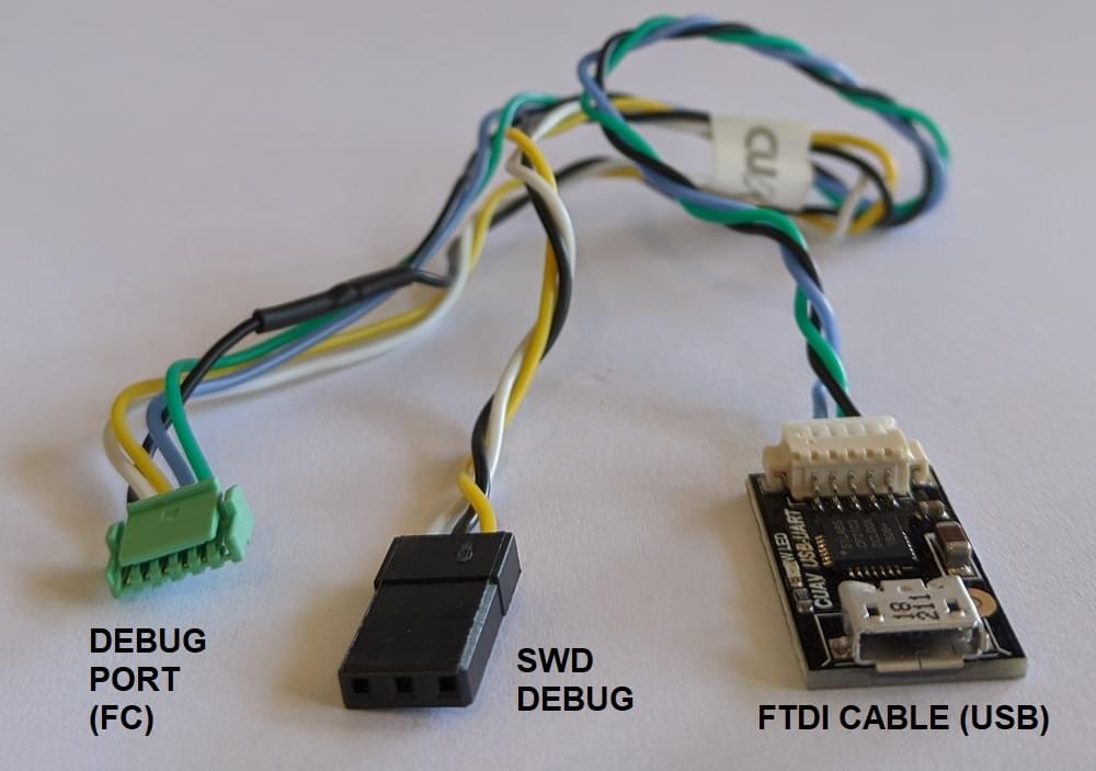
The product package includes a convenient debug cable that can be connected to the DSU7 port. This splits out an FTDI cable for connecting the PX4 System Console to a computer USB port, and SWD pins used for SWD/JTAG debugging. The provided debug cable does not connect to the SWD port Vref pin (1).

WARNING
The SWD Vref pin (1) uses 5V as Vref but the CPU is run at 3.3V!
일부 JTAG 어댑터 (SEGGER J-Link)는 Vref 전압을 사용하여 SWD 라인의 전압을 설정합니다. For direct connection to Segger Jlink we recommended you use the 3.3 Volts from pin 4 of the connector marked DSM/SBUS/RSSI to provide Vtref to the JTAG (i.e. providing 3.3V and NOT 5V).
For more information see Using JTAG for hardware debugging.
시리얼 포트 매핑
| UART | 장치 | 포트 |
|---|---|---|
| UART1 | /dev/ttyS0 | GPS |
| USART2 | /dev/ttyS1 | TELEM1 (흐름 제어) |
| USART3 | /dev/ttyS2 | TELEM2 (흐름 제어) |
| UART4 | /dev/ttyS3 | TELEM4 |
| USART6 | /dev/ttyS4 | TX는 SBUS_RC 커넥터의 RC 입력입니다. |
| UART7 | /dev/ttyS5 | 디버그 콘솔 |
| UART8 | /dev/ttyS6 | PX4IO |
주변 장치
지원 플랫폼 및 기체
일반 RC 서보 또는 Futaba S-Bus 서보로 제어 가능한 모든 멀티콥터/비행기/로버 또는 보트. The complete set of supported configurations can be seen in the Airframes Reference.
참고
Do not plug Digital or Analog PM onto connectors configured for other type of PM
If you plug an Analog PM into a digital PM connector it will stop all the I2C devices on that bus. Specifically this will stop the GPS's compass due to contention, and may also damage the FMU (longer term).
Similarly, a digital PM plugged into a analog connector will not work, and may also damage/destroy the power module (longer term).
호환성
CUAV는 몇 가지 차별화된 디자인을 채택하고, 아래에서 설명하는 일부 하드웨어와 호환되지 않습니다.
GPS not compatible with other devices
The Neo v2.0 GPS recommended for use with CUAV V5+ and CUAV V5 nano is not fully compatible with other Pixhawk flight controllers (specifically, the buzzer part is not compatible and there may be issues with the safety switch).
The UAVCAN NEO V2 PRO GNSS receiver can also be used, and is compatible with other flight controllers.
하드웨어 디버깅에 JTAG 사용
DSU7 FMU Debug Pin 1 is 5 volts - not the 3.3 volts of the CPU.
Some JTAG use this voltage to set the IO levels when communicating to the target.
For direct connection to Segger Jlink we recommended you use the 3.3 Volts of DSM/SBUS/RSSI pin 4 as Pin 1 on the debug connector (Vtref).
알려진 이슈들
The issues below refer to the batch number in which they first appear. 배치번호는 V01 뒤의 4 자리 생산날짜이며 비행 컨트롤러 측면의 스티커에 표시되어 있습니다. 예를 들어, 일련 번호 Batch V011904((V01은 V5의 번호, 1904는 생산날짜, 즉 배치번호)입니다.
SBUS/DSM/RSSI 인터페이스 Pin1 언퓨즈
WARNING
This is a safety issue.
Please do not connect other equipment (except RC receiver) on SBUS / DSM / RSSI interface - this may lead to equipment damage.
- Found: Batches V01190904xxxx
- Fixed: Batches later than V01190904xxxx