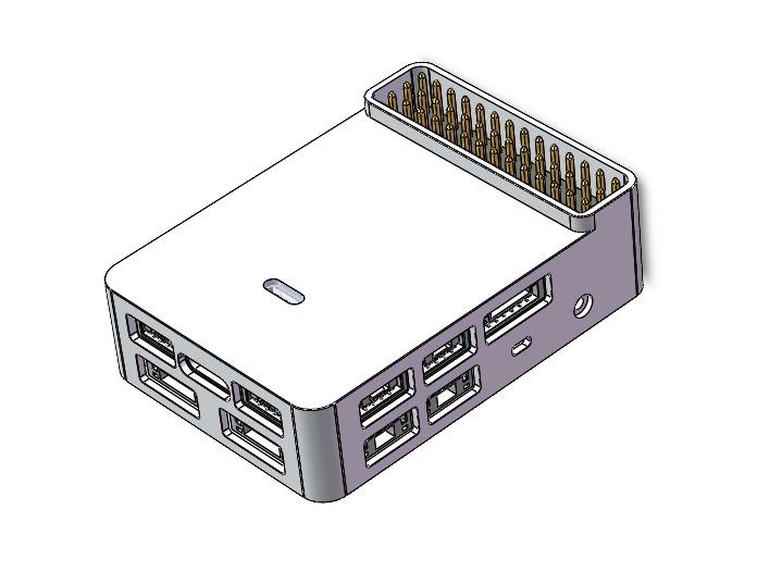
AP-H743-R1 Flight Controller
PX4 v1.17WARNING
PX4 не розробляє цей (або будь-який інший) автопілот.
The AP-H743-R1 is an advanced autopilot manufactured by X-MAV®.
The autopilot is recommended for commercial system integration, but is also suitable for academic research and any other applications. It brings you ultimate performance, stability, and reliability in every aspect.
INFO
These flight controllers are manufacturer supported.
Processors & Sensors
- FMU Processor: STM32H743VIT6
- 32 Bit Arm® Cortex®-M7, 480MHz, 2MB flash memory, 1MB RAM
- IO Processor: STM32F103
- 32 Bit Arm® Cortex®-M3, 72MHz, 20KB SRAM
- Сенсори на платі
- Accel/Gyro: ICM-42688-P*2(Version1), BMI270*2(Version2)
- Mag: QMC5883P
- Barometer: SPL06
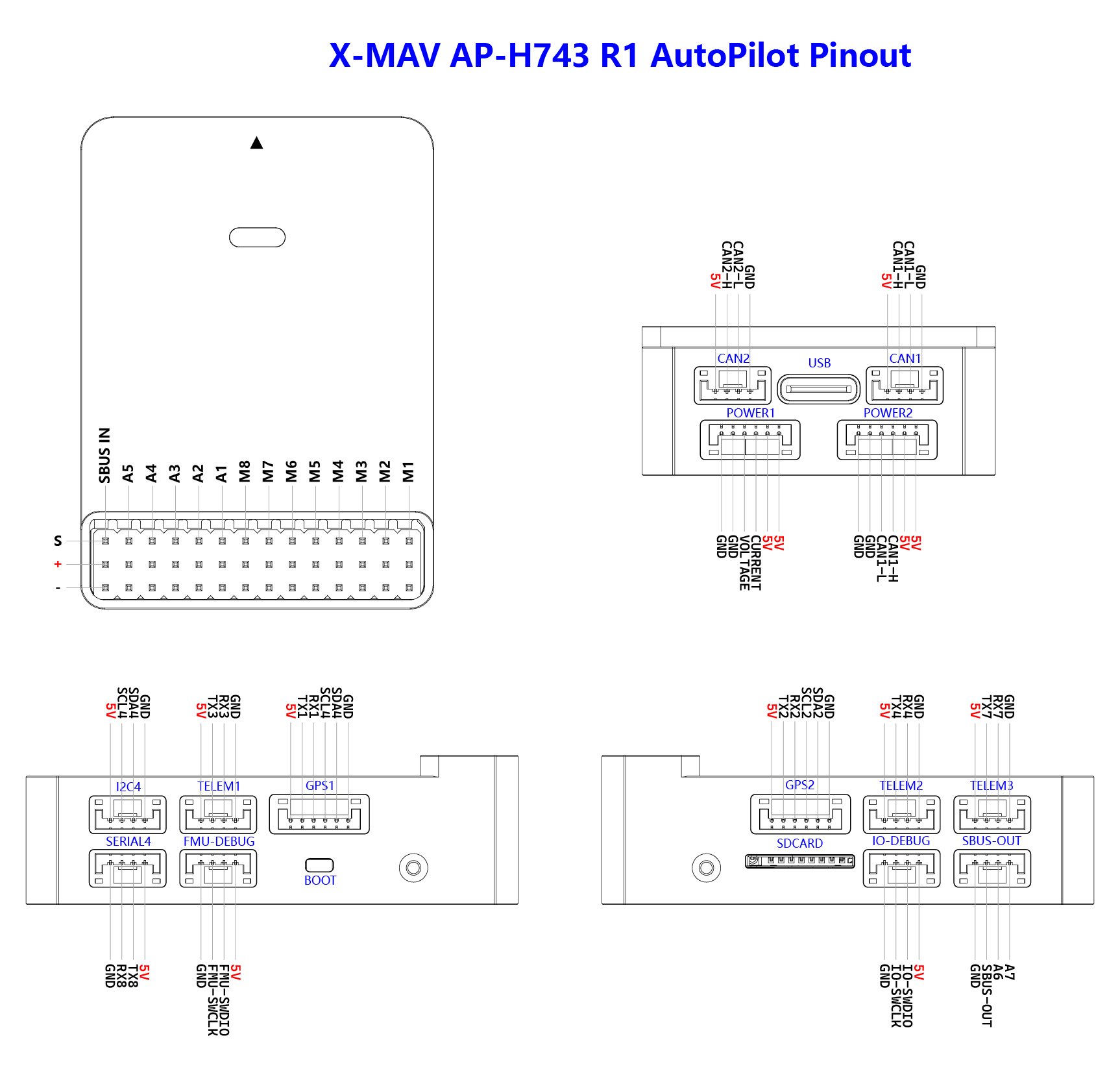
Інтерфейси
- 15x PWM Servo Outputs
- 1x Dedicated S.Bus Input
- 3x TELEM Ports
- 1x SERIAL4 Port
- 2x GPS Ports
- 1x USB Port (TYPE-C)
- 3x I2C Bus Ports
- 2x CAN Ports
- 2x Power Input Ports
- ADC Power Input
- DroneCAN/UAVCAN Power Input
- 2x Dedicated Debug Port
- FMU Debug
- IO Debug
Purchase Channels
Order from X-MAV.
Радіоуправління
A Radio Control (RC) system is required if you want to manually control your vehicle (PX4 does not require a radio system for autonomous flight modes).
Вам буде потрібно вибрати сумісний передавач/приймач та потім зв'язати їх, щоб вони взаємодіяли (прочитайте інструкції, що додаються до вашого конкретного передавача/приймача).
SBUS receivers connect to the SBUS-IN input port. CRSF receiver must be wired to a spare port (UART) on the Flight Controller. Then you can bind the transmitter and receiver together.
Налаштування послідовного порту
| UART | Пристрій | Порт |
|---|---|---|
| USART1 | /dev/ttyS0 | GPS |
| USART2 | /dev/ttyS1 | GPS2 |
| USART3 | /dev/ttyS2 | TELEM1 |
| UART4 | /dev/ttyS3 | TELEM2 |
| UART7 | /dev/ttyS4 | TELEM3 |
| UART8 | /dev/ttyS5 | SERIAL4 |
PWM Output
The AP-H743-R1 flight controller supports up to 15 PWM outputs. The first 8 outputs (labelled M1 to M8) are controlled by a dedicated STM32F103 IOMCU controller. The remaining 7 outputs (labelled A1 to A7) are the "auxiliary" outputs. These are directly attached to the STM32H743 FMU controller .
The 15 PWM outputs are:
M1 - M8 are connected to the IOMCU. A1 - A7 are connected to the FMU.
M1 - M8 support DShot and are in 3 groups:
- M1, M2 in group 1
- M3, M4 in group 2
- M5, M6, M7, M8 in group 3
The 7 FMU PWM outputs are in 3 groups:
- A1 - A4 are in one group.
- A5, A6 are in a 2nd group.
- A7 is in a 3rd group.
Channels within the same group need to use the same output rate. If any channel in a group uses DShot then all channels in the group need to use DShot.
Електричні дані
- Номінальна напруга:
- Max input voltage: 5.4V
- Вхід USB Power: 4.75~5.25V
- Вхід на серворейку: 0~9.9В
Battery Monitoring
The board has connectors for 2 power monitors.
- POWER1 -- ADC
- POWER2 -- DroneCAN
The board is configure by default for a analog power monitor, and also has DroneCAN power monitor configured which is enabled.
Збірка прошивки
To build PX4 for this target, execute:
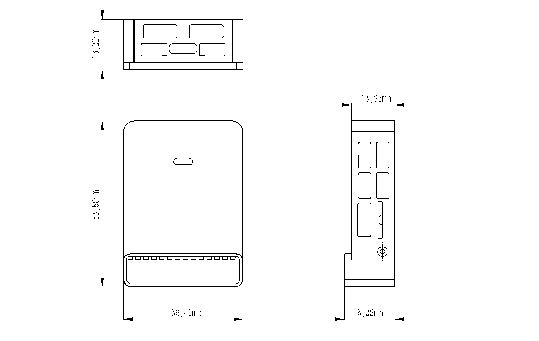
make x-mav_ap-h743r1_defaultPinouts and Size
Підтримувані платформи / Конструкції
Any multirotor/airplane/rover or boat that can be controlled using normal RC servos or Futaba S-Bus servos. The complete set of supported configurations can be found in the Airframe Reference.
Debug Port
SWD
The SWD interface operate on the FMU-DEBUG port (FMU-DEBUG).
The debug port (FMU-DEBUG) uses a JST SM04B-GHS-TB connector and has the following pinout:
| Pin | Сигнал | Вольтаж |
|---|---|---|
| 1 (red) | 5V+ | +5V |
| 2 (blk) | FMU_SWDIO | +3.3V |
| 3 (blk) | FMU_SWCLK | +3.3V |
| 4 (blk) | GND | GND |