S-Vehicle E2
WARNING
PX4 не розробляє цей (або будь-який інший) автопілот.
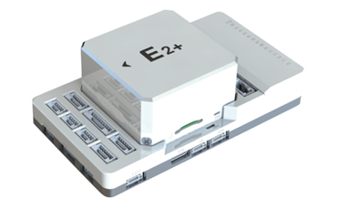
The E2 is an advanced autopilot manufactured by S-Vehicle®.
The autopilot is recommended for commercial system integration, but is also suitable for academic research and any other applications. It brings you ultimate performance, stability, and reliability in every aspect.
INFO
These flight controllers are manufacturer supported.
Processors & Sensors
- FMU Processor: STM32H753IIK6
- 32 Bit Arm® Cortex®-M7, 480MHz, 2MB flash memory, 1MB RAM
- IO Processor: STM32F103
- 32 Bit Arm® Cortex®-M3, 72MHz, 20KB SRAM
- Сенсори на платі
- Акселератор/гіроскоп: BMI088
- Accel/Gyro: ICM-42688-P
- Accel/Gyro: ICM-20649
- Mag: RM3100
- Барометр: 2x ICP-20100
Інтерфейси
- 14x PWM Servo Outputs
- 1x Dedicated R/C Input for Spektrum / DSM and S.Bus
- 1x Analog/PWM RSSI Input
- 2x TELEM Ports (with full flow control)
- 1x UART4 Port
- 2x GPS Ports
- 1x Full GPS plus Safety Switch Port (GPS1)
- 1x Basic GPS Port (with I2C, GPS2)
- 1x USB Port (TYPE-C)
- 1x Ethernet Port
- Transformerless application
- 100Mbps
- 3x I2C Bus Ports
- 1x SPI Bus
- 1x Chip Select Line
- 1x Data Ready Line
- 1x SPI Reset Line
- 2x CAN Ports
- 3x Power Input Ports
- ADC Power Input
- I2C Power Input
- DroneCAN/UAVCAN Power Input
- 2x AD Ports
- Analog Input (3.3V)
- Analog Input (6.6V - not supported by PX4)
- 1x Dedicated Debug Port
- FMU Debug
Purchase Channels
Order from S-Vehicle.
Радіоуправління
A Radio Control (RC) system is required if you want to manually control your vehicle (PX4 does not require a radio system for autonomous flight modes).
Вам буде потрібно вибрати сумісний передавач/приймач та потім зв'язати їх, щоб вони взаємодіяли (прочитайте інструкції, що додаються до вашого конкретного передавача/приймача).
Spektrum/DSM receivers connect to the DSM/SBUS RC input. PPM or SBUS receivers connect to the RC IN input port. CRSF receiver must be wired to a spare port (UART) on the Flight Controller. Then you can bind the transmitter and receiver together.
Налаштування послідовного порту
| UART | Пристрій | Порт |
|---|---|---|
| USART1 | /dev/ttyS0 | GPS |
| USART2 | /dev/ttyS1 | TELEM3 |
| USART3 | /dev/ttyS2 | Debug Console |
| UART4 | /dev/ttyS3 | UART4 |
| UART5 | /dev/ttyS4 | TELEM2 |
| USART6 | /dev/ttyS5 | PX4IO/RC |
| UART7 | /dev/ttyS6 | TELEM1 |
| UART8 | /dev/ttyS7 | GPS2 |
PWM Output
The E2-Plus flight controller supports up to 14 PWM outputs. The first 8 outputs (labelled M1 to M8) are controlled by a dedicated STM32F103 IOMCU controller. The remaining 6 outputs (labelled 9 to 14) are the "auxiliary" outputs. These are directly attached to the STM32H753 FMU controller .
The 14 PWM outputs are:
M1 - M8 are connected to the IOMCU A1 - A6 are connected to the FMU
M1 - M8 support DShot and are in 3 groups:
- M1, M2 in group 1
- M3, M4 in group 2
- M5, M6, M7, M8 in group 3
The 6 FMU PWM outputs are in 2 groups:
A1 - A4 are in one group. A5, A6 are in a 2nd group.
Channels within the same group need to use the same output rate. If any channel in a group uses DShot then all channels in the group need to use DShot.
Електричні дані
- Номінальна напруга:
- Максимальна вхідна напруга: 5,7 В
- Вхід USB Power: 4.75~5.25V
- Вхід на серворейку: 0~9.9В
- Номінальний струм:
- Комбінований обмежувач вихідного струму TELEM1 і GPS2: 1,5 А
- Комбінований обмежувач вихідного струму всіх інших портів: 1.5A
Battery Monitoring
The board has connectors for 3 power monitors.
- POWER1 -- ADC
- POWER2 -- DroneCAN
- POWER3 -- I2C
The board is configure by default for a analog power monitor, and also has DroneCAN power monitor and I2C defaults configured which is enabled.
The default PDB included with the E2+ is analog and must be connected to POWER1.
Збірка прошивки
To build PX4 for this target, execute:
make svehicle_e2_defaultВідладочний порт
The PX4 System Console and SWD Interface operate on the FMU Debug port.
| Pin | Сигнал | Вольтаж |
|---|---|---|
| 1 (red) | 5V+ | +5V |
| 2 (blk) | DEBUG TX (OUT) | +3.3V |
| 3 (blk) | DEBUG RX (IN) | +3.3V |
| 4 (blk) | FMU_SWDIO | +3.3V |
| 5 (blk) | FMU_SWCLK | +3.3V |
| 6 (blk) | GND | GND |
Інформацію про використання цього порту див:
- SWD Debug Port
- PX4 System Console (Note, the FMU console maps to USART3).
- All ports use GH1.25 ,power ports use ports on E2 uses the 6 circuit 2.00mm Pitch CLIK-Mate Wire-to-Board PCB Receptacle.
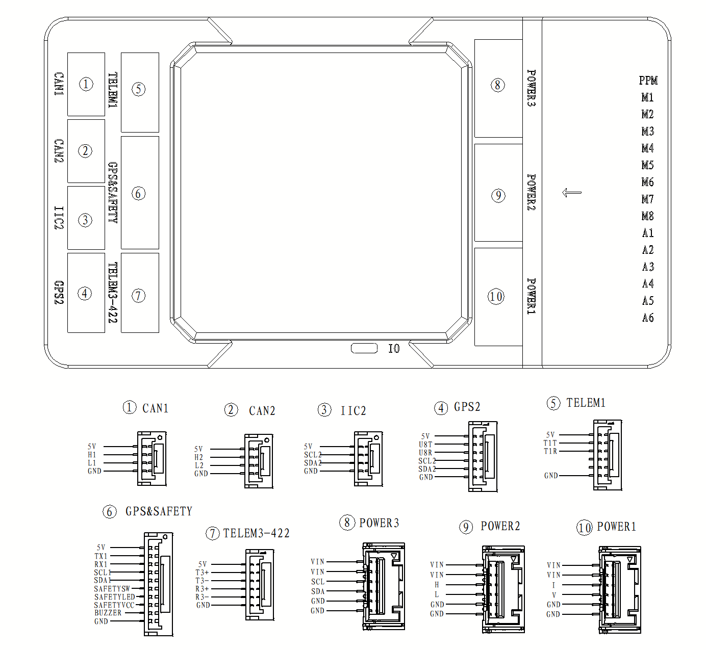
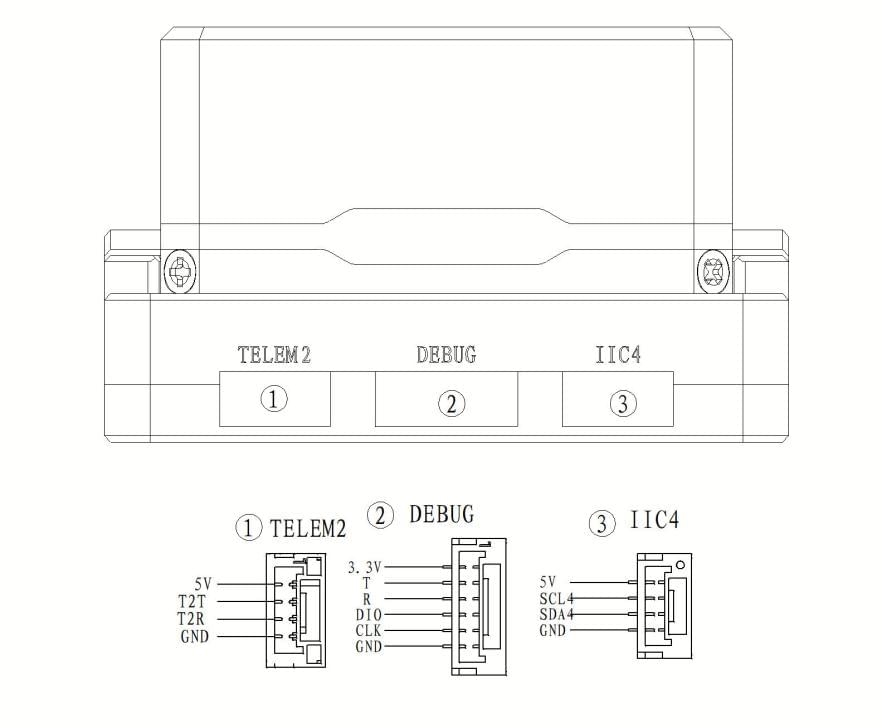
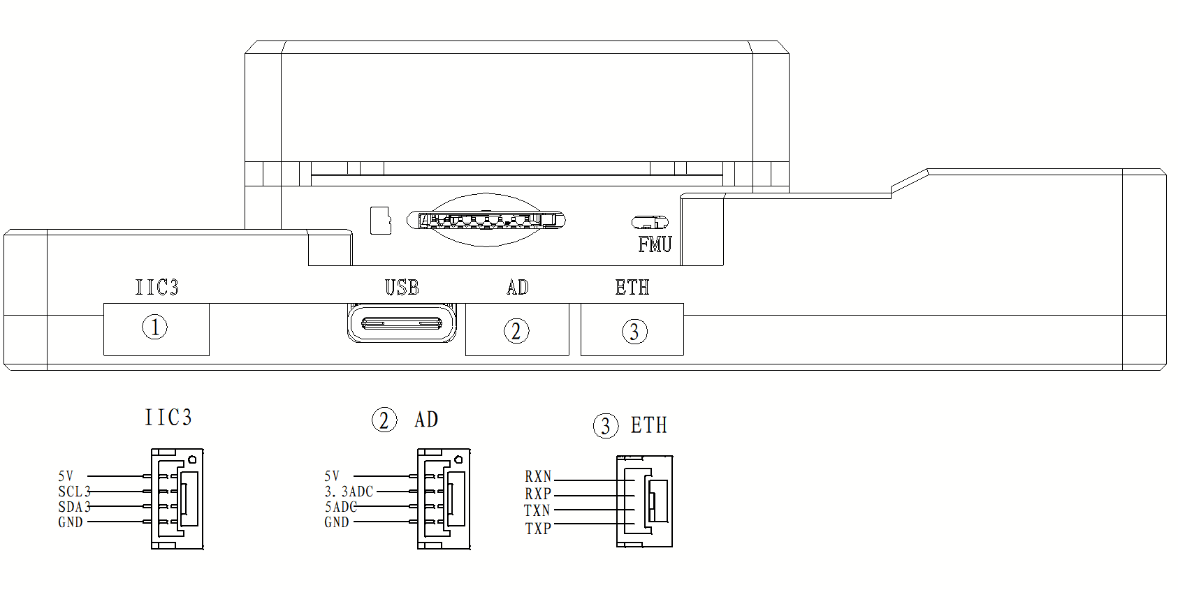
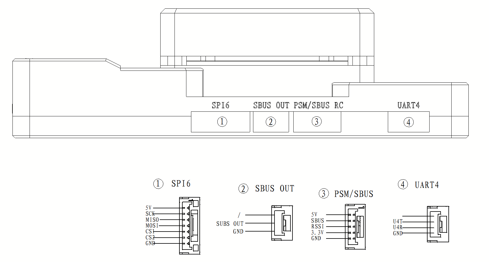
Схема розташування виводів
Підтримувані платформи / Конструкції
Any multirotor/airplane/rover or boat that can be controlled using normal RC servos or Futaba S-Bus servos. The complete set of supported configurations can be found in the Airframe Reference.