Модуль WiFi ESP8266
ESP8266 та його клони - це недорогі та легко доступні модулі Wi-Fi з повним стеком TCP/IP та можливістю мікроконтролера. Вони можуть використовуватись з будь-яким контролером Pixhawk.
TIP
ESP8266 is the defacto default WiFi module for use with Pixracer (and is usually bundled with it).
Де купити
Модуль ESP8266 легко доступний від ряду постачальників. Нижче наведено перелік кількох виконавців.
Більшість модулів підтримують тільки 3.3 V у той час як деякі контролери польоту (наприклад, Pixhawk 4) вивід на 5V (вам потрібно перевірити сумісність і виконати зниження напруги при необхідності).
Модулі, що приймають постачання 3.3V:
- WRL-17146 (Sparkfun)
Модулі, що приймають постачання 5.3V:
AI Thinker (Banggood)
AlphaUAVLink (Banggood)
Kahuna (Beyond Robotix)
A plug and play ESP8266 module.
The Kahuna comes with a cable to connect directly to the Pixhawk-standard
TELEM1orTELEM2ports. It is pre-flashed with the latest firmware, and has au.flconnector for an external antenna. At most you may need to set the baud rate parameter, which forTELEM1isSER_TEL1_BAUD = 57600 (57600 8N1). The User Guide include WiFi setup and other relevant information.
Pixhawk/PX4 Setup & Configuration
TIP
You may first need to update the radio with PX4-compatible ESP8266 firmware (see below). Інструкції по виготовленню повинні пояснити, чи це потрібно.
Підключіть свій ESP8266 до вашого польотного контролера серії Pixhawk (наприклад, Pixracer) на будь-якому вільному UART.
Підключіть контролер польоту до вашої наземної станції через USB (так як WiFi ще не повністю налаштований).
Використання Від QGroundControl:
- Load recent PX4 firmware onto the flight controller.
- Configure the serial port used to connect the ESP8266. Не забудьте встановити швидкість передачі даних на 921600, щоб відповідати значенню, встановленому для ESP8266.
- Configure MAVLink on the corresponding serial port in order to receive telemetry and transmit commands over the ESP8266.
Після того, як ви налаштували послідовний порт керування польотом для підключення до радіо, ви можете від'єднати фізичне USB-підключення між наземною станцією та транспортним засобом.
Підключення через ESP8266 до QGC
Модуль надає точку доступу WiFi, яку ваш комп'ютер земної станції може використовувати для підключення до літального апарату.
INFO
The settings for the ESP8266 hotspot should be provided with the board (e.g. typically printed on the reverse side of the board or on the packaging).
Типові налаштування заводської мережі:
- SSID: PixRacer
- Password: pixracer
- WiFi Channel: 11
- UART speed: 921600
Інші модулі можуть використовувати налаштування, подібні до цього:
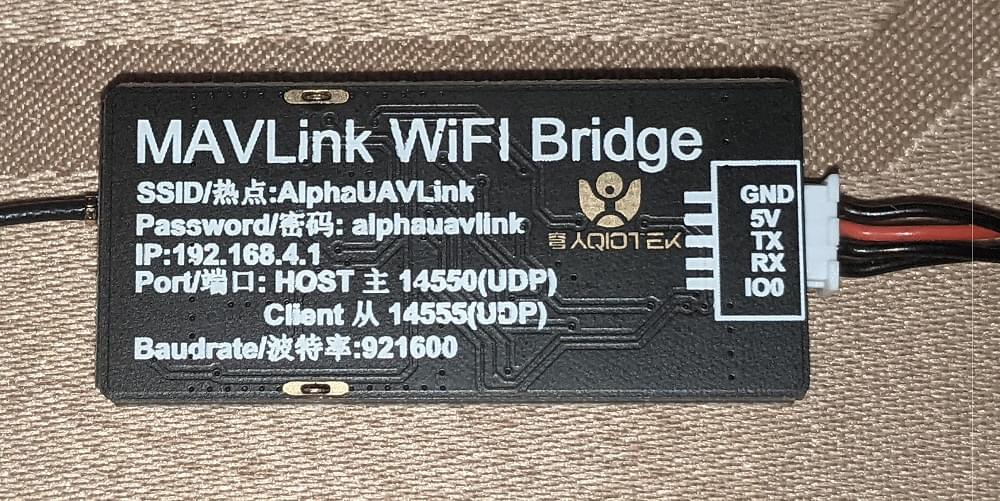
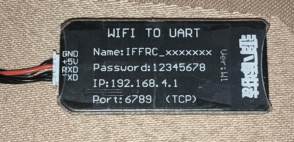
- SSID: IFFRC_xxxxxxxx
- Password: 12345678
- IP: 192.168.4.1
- Port: 6789 (TCP)
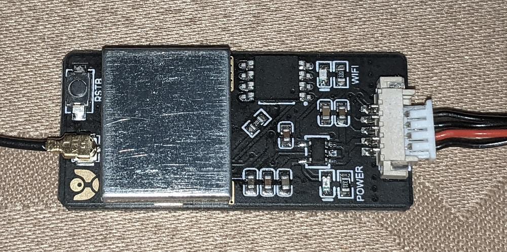
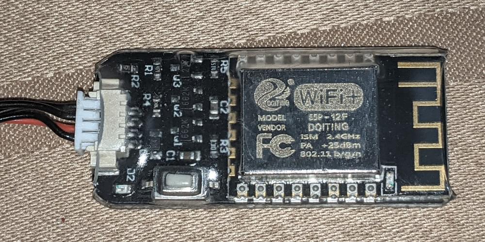
Приклади дошок від AlphaUILink та DOITING показані нижче:
On your wifi-enabled QGroundControl ground station computer/tablet, find and connect to the open wireless network for your ESP8266. On a Windows computer the connection settings for a network with name Pixracer and default password pixracer point will look like this:
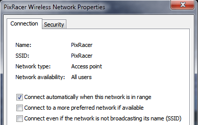
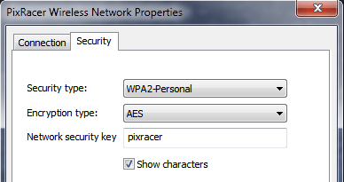
QGroundControl will automatically connect to the vehicle when the ground station computer is attached to a WiFi access point named "Pixracer".
Якщо ви використовуєте модуль з будь-яким іншим ім'ям WiFi, вам потрібно вручну налаштувати підключення WiFi QGroundControl, як показано в наступному розділі.
Налаштувати QGC з нестандартними WiFi підключеннями
QGroundControl will automatically connect to the vehicle when the ground station computer is attached to the "Pixracer" WiFi access point. Для будь-якого іншого імені точки доступу вам потрібно буде вручну створити спеціальне комунікаційне посилання:
- Go to Application Settings > Comm Links
- Додайте нове підключення з відповідними налаштуваннями.
- Select the new connection, and click Connect.
- Автомобіль тепер повинен підключатися
Перевірити
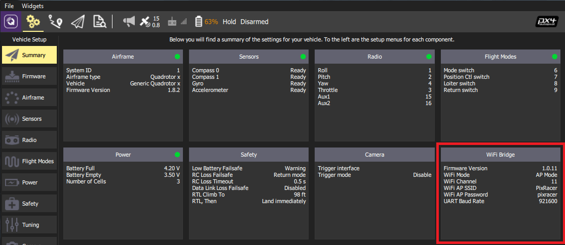
Тепер ви повинні бачити рух HUD на вашому комп'ютері QGC через бездротове з'єднання і мати можливість переглядати панель підсумків для моста WiFi ESP8266 (як показано нижче).
TIP
If you have any problem connecting, see QGC Usage Problems.
Прошивка/прошивка ESP8266 (розширений)
Модулі ESP8266 від різних виробників можуть не мати встановленого відповідного прошивкового забезпечення ESP8266 наперед. Інструкції нижче пояснюють, як налаштувати та запустити тести локально.
Побудувати з Джерел
The firmware repository contains instructions and all the tools needed for building and flashing the ESP8266 firmware.
Оновлення прошивки OTA
If you have firmware 1.0.4 or greater installed, you can do the update using the ESP's Over The Air Update feature. Just connect to its AP WiFi link and browse to: http://192.168.4.1/update. Потім ви можете вибрати файл прошивки, який ви завантажили вище, та завантажити його на модуль WiFi.
TIP
This is the easiest way to update firmware!
Прошивка прошивки ESP8266
Before flashing, make sure you boot the ESP8266 in Flash Mode as described below. If you cloned the MavESP8266 repository, you can build and flash the firmware using the provided PlatformIO tools and environment. If you downloaded the pre-built firmware above, download the esptool utility and use the command line below:
sh
esptool.py --baud 921600 --port /dev/your_serial_port write_flash 0x00000 firmware_xxxxx.binДе:
- firmware_xxxxx.bin is the firmware you downloaded above
- your_serial_port is the name of the serial port where the ESP8266 is connected to (
/dev/cu.usbmodemfor example)
Проводка для Прошивання Програмного Забезпечення
WARNING
Most ESP8266 modules support 3.3 volts (only), while some flight controllers (e.g. Pixhawk 4) output at 5V. Перевірте сумісність та знизьте напругу, якщо це потрібно.
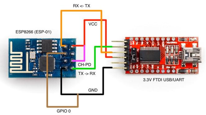
There are various methods for setting the ESP8266 into Flash Mode but not all USB/UART adapters provide all the necessary pins for automatic mode switching. In order to boot the ESP8266 in Flash Mode, the GPIO-0 pin must be set low (GND) and the CH_PD pin must be set high (VCC). Ось як виглядає моя власна налаштування:
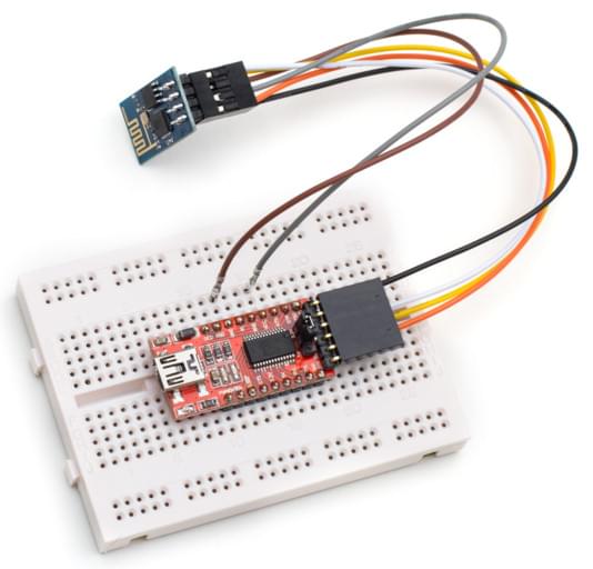
Я побудував кабель, де RX, TX, VCC та GND правильно підключені безпосередньо від адаптера FTDI до ESP8266. З ESP8266 я залишив дві проводи, підключені до GPIO-0 та CH_PD вільними, щоб я міг завантажити його або зазвичай, або в режимі флеш, підключивши їх до GND та VCC відповідно.
ESP8266 (ESP-01) Pinout
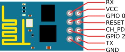
Діаграма миготіння за допомогою адаптера USB/UART FTDI
